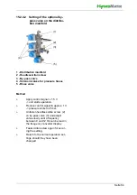
Page 71
14. Faults
14.1 Fault Management
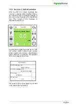
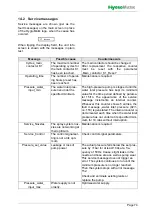
In the event of a fault, the humidification/cool-
ing is haltet. The relevant display field is then
shown instead of the HygroMatik logo. The
display field shows a warning symbol, the
„Fault“ message and - in paranthesis - the
fault code:
When touching the fault message display
field, the unit info screen opens with the fault
message in plain text and information con-
cerning the unit and its current state.
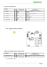
The majority of fault messages is additionally
accompanied by the flashing of one or more
icons, allowing for a first limitation of the
cause of fault.
14.1.1 Table of fault messages, pos-
sible causes and counter-
measures
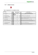
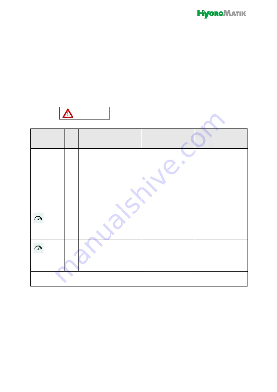
Fault (001
)
e.g.:
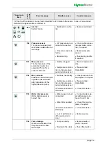
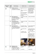
These icons
flash
Fault
Code
Fault message
Possible cause
Counter measure
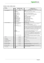
002
Expansion board
Expansion board not detec-
ted by the sofware
•
p.c.b. connection not
o.k.
•
Check firm connec-
tion of boards
•
p.c.b. not present or
defective
•
Connect board,
replace board if defec-
tive
•
CAN bus addressing
not correct
•
Check DIP switch
settings on extension
board (see fig. in sec-
tion 3.4).
022
*)
Input_current_min
The min. value of the input
signal is no plausibel
•
Sensor, wiring or
signal source defective
•
Check sensor, wiring
and signal source, if
relevant
024
025
*)
Input_resistance_OC
Input_resistance_SC
The resistance measured is
not correct („infinite“ or
„zero“, resp.)
•
Sensor, wiring or
signal source defective
•
Check sensor, wiring
and signal source, if
relevant
•
Input stage defective
•
Replace mainboard
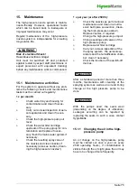
*) When the PI controller is in use, fault codes 022 to 025 relate to the sensor. In case of an external
controller, the signal source is referred to.

