Page 89
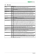
19. Glossary
Term
[Index] Explanation
Actual value
1
The actual value is the measured value of a physical quantity, which is compared with the
Set
value [3]
during the control process and may give rise to a readjustment, if required.
Relative humidity (r.h.)
2
The relative humidity (r.h.) describes the maximum percentage of moisture which the ambient air can hold at
a certain temperature.
Set value
3
The set value of a physical quantity (e.g. the
r. h. [2
] ) is the set target for a control process.
Humidification output
4
Demand
5
The demand describes the dimensionless control signal processed by the control system which is
converted into a proportional
Internal actuator signal [42]
for the power control for steam generation.
Hygrostat
6
Sensor with switching function for the
Relative humidity (r.h.) [2]
in rooms. The trigger point for the
switching function with potential free contacts can be set mechanically. The hygrostat can be used to control
1 step operation [44]
or in the
Interlock (safety) system [11]
to protect against excess humidity.
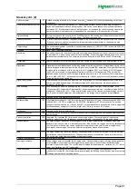
Update function
7
The update function provides the control with an update of parameter settings which is stored on an external
USB memory stick. The "Update function" parameter is a read-only value which can be used to read out the
status of the update.
SI system of units
The system of units with the pressure specified in bar.
Initialisation
The control performs a self-test, during which the welcome screen with the software version is displayed.
After the parameter settings and measured values have been read in, the
Main screen [14]
is shown on
the display.
Interlock (safety) system
11
The hardware interlock (safety) system makes it possible to immediately interrupt steam production, e.g.
using an emergency stop button
.
The interlock (safety) system must be closed to operate the unit. The
interlock (safety) system must be implemented on-site with one or several potential free contacts (switched
in series). It is connected to the control at terminals 1 and 2, with terminal 1 carrying 230 VAC as standard.
In a special design (e.g. for the U.S. market), the interlock (safety) system is converted to low voltage
through the additional use of a relay (K21) to meet local safety requirements. Instead of terminals 1 and 2 on
the control, a potential free connection of the relevant DIN rail terminals must then be implemented on-site. If
the interlock (safety) system is opened, the status of the unit changes to "Interlock (safety) system open".
Software control command
12
Coded command, which is, for example, sent from the building control system or a PLC via the
Communication interface [13]
to the control. The command set available is listed in separate
documentation, which is available from HygroMatik on request.
Communication interface
13
Serial computer interface for remote control of the unit using, for example, the
Modbus [17]
RTU protocol.
Main screen
14
Screen content during the normal operation of the unit. The main screen includes the main display (in the
middle of the screen) and the status icons (left and right of the main display).
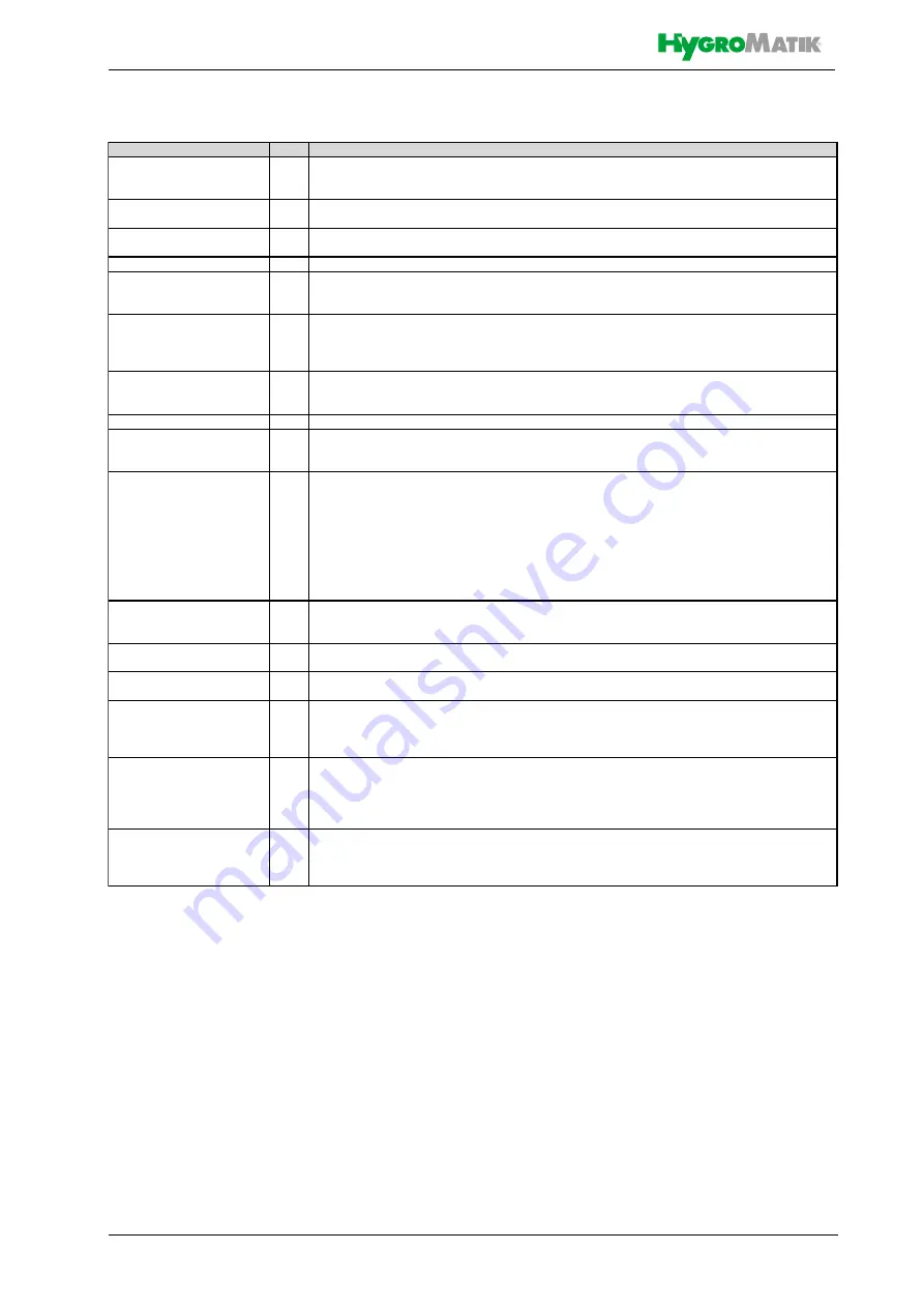
Modbus
17
Modbus is a communications protocol for serial data transmission for the remote control of units, which is
widely used in industry. HygroMatik controls use the MODBUS - RTU (remote terminal unit) variant.
Separate documentation is available upon request from HygroMatik.
Flushing of dead-end line
27
When this function is activated, the feed water line is flushed during operation phases in which there are no
requests in order to prevent germ formation. For this purpose, the inlet solenoid valve and the flushing
solenoid valve are activated at the same time. The "Flushing_of_dead-end line_interval" parameter
determines when flushing starts after a humidification request was not received, the "Flushing_of_dead-end
line_duration" parameter determines how long flushing takes.
Service_main_contactor
34
The operating cycles of the main contactor is recorded by a counter and compared to a factory-set default
value by the software. When the default value is reached, the "Service_main_contactor K1" message is
displayed on the screen. After the main contactor has been replaced, the counter must be reset with the
parameter "Main_contactor_Reset".

