Page 19
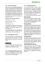
4.5.4 Aerosol separators
There are no more atomised water droplets
in the air stream behind the HygroMatik high-
pressure nozzle system(if the environmental
parameter specifications are complied with).
For this purpose the aerosol separators are
used that may be configured in a 1-step or 2-
step arrangement, depending on the applica-
tion requirements.. The dry trap pads exhibit
a low pressure drop (30 Pa per stage at an
air velocity of 2.0 m/s and an average air
density of 1.2 kg/m³ ).
Specified environmental parameters
Air velocity: 0,9 – 2,8 m/s
relative humidity: 5 – 95% r.F.
Temp IN: 20 - 60°C
Temp OUT: min. 15°C
If it is outside this range it can cause moisture
breakthrough downstream of the aerosol
separators - in such cases please first con-
tact HygroMatik.
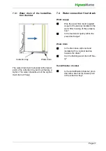
The aerosol separators are inserted into the
humidification chamber via guide rails and
are hence easy to remove for servicing.
4.5.5 Humidification section
The section between the spray system and
the aerosol separators is called the 'humidifi-
cation section' in this system. It is unob-
structed and hence easy to monitor and
clean.
It is recommended that the humidity sensor is
mounted in a distance of at least 5 m with
respect to the humidification system.
For a total standard installation length of 1.5
m for the HygroMatik high-pressure nozzle
system the humidification section should
have a length of at least 0.9 m. If this is not
the case, pls. contact HygroMatik.
4.6 Flushing functions
The nozzle system offers a number of flush-
ing variants in order to cope with the hygienic
and maintenance oriented requirements.
Flushing can be accomplished with supply
water pressure only or through use of the
vane pump, depending on a parameter set-
ting. Also, the duration of the flushing func-
tion may be altered by the setting.
The following flushing variants are supported:
Manual flushing
Manual flushing is startet by setting a param-
eter in the „Adiabate functions“ function
group and stopped by resetting the parame-
ter. The water inlet solenoid valve and the
flushing valve are both opened.
Dead leg flushing
Dead leg flushing is to prevent microbial con-
tamination due to water resident in the water
supply. When dead leg flushing is activated,
after a wait time defined by a parameter, a
fully automatic flushing of the system is
accomplished with line pressure while the
inlet solenoid and the flushing solenoid are
open. It is not required that the safety (inter-
lock) system is closed for that purpose. The
duration of the flushing may be varied by the
setting of a parameter.
Hygiene flushing
The need for hygiene flushing comes from
VDI 6022. After a settable wait time with no
demand present, the whole water system
with all of the nozzle segments must be
flushed (VDI 6022 requires that the wait time
is not longer than 48 hours).
Optimized flushing on demand
Internal algoritms in the control program
monitor the operating conditions and trigger
the flushing of the nozzle segments for
humidification or the nozzle segment for cool-
ing (if present). These flushings follow a
sequence that is predefined in the control
program.
Please note


