Page 12
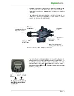
Arranged in the brine tank is a stand pipe holding a riser pipe for
brine sucking. The bottom end of the riser pipe features a ball
valve that blocks sucking when the brine level has sunk accord-
ingly. The riser pipe top end is connected to the control valve
through a brine tube.
The control valve is connected to the house water installation
either directly or via a (optionally available) mounting block
through hoses for water inlet and water outlet (optionally avail-
able water connection set including titration kit may be used).
Hose connections make use of the provided BSPT adaptors
(BSPT = British Standard Pipe Thread).
Pendulum systems feature a single control valve with the
Principle design of WaterLine softener device WL-S
Control valve
Regenerations waste water connection
Soft water
connection
Brine tank
Brine tube
Raw water
connection
Resin filling
Riser pipe
Overflow
Floor drain
Riser pipe
w. ball valve
Pressure tank
Inserted
Riser pipe
Top nozzle
Bottom nozzle
*) Inserted floor screen only when resin capacity is 100 m
3
x °dH or higher
floor screen *)
Brine
filling
Waste water
hose
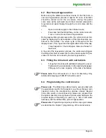
Principle design of WaterLine softener device WL-D/DP
Brine tank
Brine tube
Raw water
connection
Resin filling
Riser pipes
Overflow
Floor drain
2
nd
pressure
Control valve
Riser pipe
w. ball valve
Soft water
connection
Pressure tank
Tubing
Top nozzles
Bottom nozzles
Stand pipe
Regeneration waste water connection
*) Inserted floor screen only when resin capacity is 100 m
3
x °dH or higher
Inserted
floor screen *)
tank
Brine
filling
Waste water
hose
connection
Water inlet
and outlet
Wastewater
Brine tube
Blending
valve
Electronic control
with Display and
Control valve for WL-S,
connections
control panel
connection
Summary of Contents for WaterLine Double
Page 43: ...Page 43 This page intentionally left blank ...
Page 44: ......


