CHASSIS 6-29-1
31
●
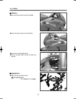
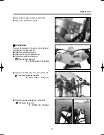
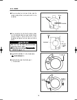
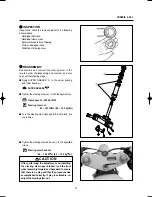
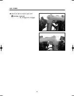
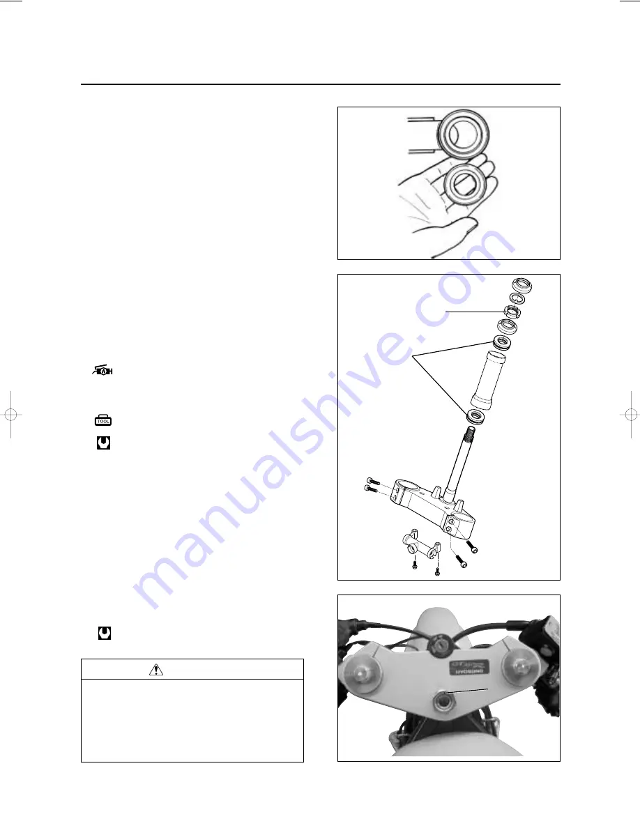
Tighten the steering stem nut
②
with the special tool.
●
Turn the steering stem right and left, lock-to-lock, five
or six times.
●
Tighten the steering stem head nut
③
to the specified
torque.
Clamp wrench : 09940-10122
Steering stem nut
: 80 ~ 100 N
∙
∙
m (8.0 ~ 10.0 kg
∙
∙
m)
CAUTION
After performing the adjustment and installing
the steering stem upper bracket, rock the front
wheel assembly forward and backward to ensure
that there is no play and that the procedure was
accomplished correctly. If play is noticeable, re-
adjust the steering stem nut.
◉
◉
INSPECTION
Inspect and check the removed parts for the following
abnormalities.
∙
Handlebar distortion.
∙
Handlebar clamp wear.
∙
Abnormality operation of bearing.
∙
Worn or damaged races.
∙
Distortion of steering stem.
◉
◉
REASSEMBLY
Reassemble and remount the steering stem in the
reverse order of disassembly and removal, and also
carry out the following steps :
●
Apply SUPER GREASE
“
A
”
to the upper bearing
and lower bearing
①
.
①
②
Steering stem head nut
: 80 ~ 100 N
∙
∙
m (8.0 ~ 10.0 kg
∙
∙
m)
SUPER GREASE
“
“
A
”
”
③
GT250/125R(SM)내지 2006.7.26 1:58 PM 페이지31
001 PagePro 9100 300DPI 100LPI
Summary of Contents for Aquila GT250 R Ej
Page 3: ...2 NOTE Difference between photographs and actual motorcycles depends on the markets ...
Page 5: ...4 ...
Page 6: ...5 GENERAL INFORMATION EXTERIOR ILLUSTRATION 6 1 6 SPECIFICATIONS 7 1 8 CONTENTS 1 ...
Page 10: ...9 MAINTENANCE PROCEDURES CARBURETOR 10 2 7 CLUTCH 11 2 8 1 CONTENTS 2 2 PERIODIC MAINTENANCE ...
Page 14: ...13 LAMP 14 5 16 1 ELECTRICAL SYSTEM 5 CONTENTS ...
Page 18: ...17 5 17 2 ELECTRICAL SYSTEM ...
Page 19: ...18 ...
Page 20: ...19 CHASSIS EXTERIOR PARTS 20 6 1 1 HANDLEBARS 25 6 12 1 STEERING 29 6 27 CONTENTS 6 ...
Page 34: ...33 SERVICING INFORMATION SERVICE DATA 34 7 20 WIRING DIAGRAM 35 7 31 CONTENTS 7 ...

