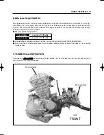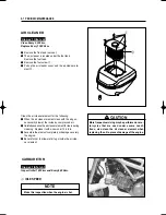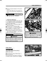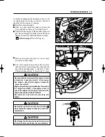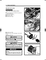
[
REAR CYLINDER
]
[
FRONT CYLINDER
]
MAINTENANCE PROCEDURES
This section describes the service procedure for
each section of the periodic maintenance.
VALVE CLEARANCE
The valve clearance specification is different for
intake and exhaust valves.
Valve clearance adjustment must be checked and
adjusted,
1) at the time of periodic inspection,
2) w h e n t h e v a l v e m e c h a n i s m i s s e r v i c e d , a n d
3 ) when the camshaft is disturbed by removing it
for servicing.
●
Remove the spark plug. (Refer to page 2-5)
●
Remove the fuel tank. (Refer to page 4-1)
●
Remove the radiator. (Refer to page 5-2)
●
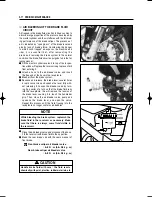
Remove the cylinder head cover bolt
①
and
②
.
●
Remove the magneto cover plug
③
and the tim-
ing inspection plug
④
.
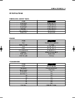
0.1
�
0.2 mm (0.004 ~ 0.008 in)
0.2
�
0.3 mm (0.008 ~ 0.012 in)
IN.
EX.
Standard (When cold)
Valve clearance
Thickness gauge : 09900-20806
●
Rotate the magneto rotor counter-clockwise to set
the front cylinder
’
s piston at TDC (Top Dead
Center) of the compression stroke.
(Rotate the rotor until
“
|
F
”
line on the rotor is aligned
with the center of hole on the crankcase.)
●
To inspect the front cylinder
’
s valve clearance, insert
the thickness gauge to the clearance between the
camshaft and the tappet.
Inspect Interval
Inspect Initial 1,000 km and Every 6,000 km.
CAUTION
The clearance specification is for COLD state.
2-3 PERIODIC MAINTENANCE
②
①
③
④
Summary of Contents for GT 650
Page 5: ...NOTE Difference between photographs and actual motorcycles depends on the markets ...
Page 13: ...1 7 GENERAL INFORMATION EXTERIOR ILLUSTRATION ...
Page 102: ...CARBURETOR 4 3 FUEL SYSTEM ...
Page 138: ...LAMP HEADLAMP TURN SIGNAL LAMP TAIL BRAKE LAMP ELECTRICAL SYSTEM 6 16 ...
Page 158: ...7 15 CHASSIS FRONT FORK ...

