30
4-1-15 EI SYSTEM DIAGNOSIS
CAUTION
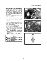
Do not disconnect the ECU lead wire couplers, before checking the malfunction code, or the malfunction
code memory is erased and the malfunction code can not be checked.
Confirm the malfunction code after turn the ignition switch “ON” position or cranking the engine for few
seconds.
Mode select switch : 09900-27000
⊙
⊙
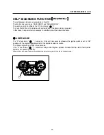
DEALER MODE
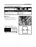
The defective function is memorized in the ECU.
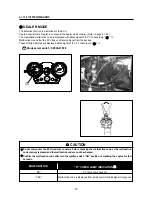
Use the special tool’s coupler to connect to the dealer mode coupler. (Refer to page 4-1-20)
The memorized malfunction code is displayed with blinks signal of the “FI” check lamp “ ”
.
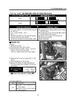
Malfunction means that the ECU does not receive signal from the devices.
These affected devices are displayed blinks signal of the “FI” check lamp “ ”
.
MALFUNCTION
“NO”
“YES”
Malfunction code is displayed from small numeral blinks signal to large one.
“FI” check lamp goes off.
“FI” CHECK LAMP INDICATION
Summary of Contents for GT250 EI
Page 1: ...SERVICE MANUAL 99000 95620 SERVICE MANUAL...
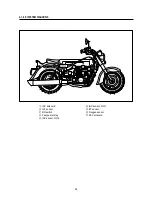
Page 7: ...6 1 6 1 GENERAL INFORMATION EXTERIOR PHOTOGRAPH...
Page 8: ...7 GENERAL INFORMATION 1 6 2 EXTERIOR PHOTOGRAPH...
Page 15: ...14...
Page 63: ...62 4 2 1 FUEL SYSTEM AND THROTTLE BODY FUEL SYSTEM...
Page 68: ...67 FUEL SYSTEM AND THROTTLE BODY 4 2 6 THROTTLE BODY...
Page 79: ...78...
Page 95: ...94 7 31 1 SERVICING INFORMATION WIRING DIAGRAM...
Page 96: ...95 SERVICING INFORMATION 7 31 2...
Page 97: ...96 7 32 1 SERVICING INFORMATION WIRING DIAGRAM...
Page 98: ...97 SERVICING INFORMATION 7 32 2...
Page 99: ...98 7 32 3 SERVICING INFORMATION WIRING DIAGRAM...
Page 100: ...99 SERVICING INFORMATION 7 32 4...
Page 101: ...Prepared by 1st Ed APR 2009 Manual No 99000 95620 Printed in Korea...
Page 102: ...SERVICE MANUAL S T Motors Co Ltd...


