background image

ENGINE

3-12

Service limit

0.03 mm (0.0012 in)

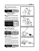
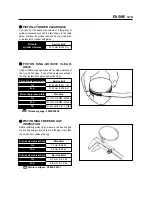
VALVE HEAD RADIAL RUNOUT

Place a dial gauge as shown and measure valve head
radial runout.
If the service limit is exceeded, replace the valve.

Valve head radial

runout

Dial gauge : 09900-20606
Magnetic stand : 09900-20701
V-block : 09900-21304

Dial gauge : 09900-20606
Magnetic stand : 09900-20701

Micrometer(0~25 mm) : 09900-20201

Standard

0.010

0.037 mm

(0.0004

0.0015 in)

0.030

0.057 mm

(0.0012

0.0022 in)

Valve stem diameter

IN.

EX.

Standard

4.975~4.990 mm (0.1959 0.1965 in)

4.955~4.970 mm (0.1951 0.1957 in)

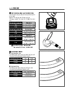
VALVE STEM DIAMETER

Measure the valve stem outside diameter.
If the diameter measured exceeds the standard, replace 
the valve.

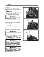
VALVE GUIDE-VALVE STEM CLEAR-

ANCE

Measure the clearance in the valve guide-valve stem, by 
rigging up the dial gauge as shown. If the clearance is
measured exceeds the limit specified below, then deter-
mine whether the valve or the guide should be replaced
to reduce the clearance to within the standard range:

Service limit

41.65 mm (1.64 in)

Valve spring free 

length(IN. & EX.)

Venier calipers : 09900-20101

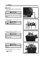
VALVE SPRING

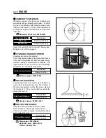
The force of the coil spring keeps the valve seat tight. A
weakened spring results in reduced engine power out-
put and often accounts for the chattering noise coming
from the valve mechanism.
Check the valve springs for proper strength by measur-
ing their free length and also by the force required to
compress them. If the spring length is less than the ser-
vice limit or if the force required to compress the spring
does not fall within the specified range, replace both the
inner and outer springs as a set.

Valve guide-valve stem clearance

IN.

EX.

Summary of Contents for KARION RT125

Page 1: ...SERVICE MANUAL 99000 94610 SERVICE MANUAL HYOSUNG MOTORS MACHINERY INC ...

Page 2: ...ual contains an introductory description on HYOSUNG and procedures for its inspection service and overhaul of its main components Other information considered as generally known is not included Read GENERAL INFORMATION section to familiarize yourself with outline of the vehicle and MAINTENANCE and other sections to use as a guide for proper inspec tion and service This manual will help you know th...

Page 3: ...are listed on the previous page as GROUP INDEX select the section where what you are looking for belong 3 Holding the manual as shown at the right will allow you to find the first page of the section easily 4 On the first page of each section its contents are listed Find the item and page you need COMPONENT PARTS Example Rear wheel Rear brake ...

Page 4: ...AD LOCK Apply or use brake fluid Measure in voltage range Measure in resistance range Measure in current range Use special tool Torque control required Data beside it indicates specified torque Apply oil Use engine oil unless otherwise specified Apply SUPER GREASE A Apply SILICONE GREASE Apply MOLY PASTE Apply BOND 1215 DEFINITION SYMBOL DEFINITION SYMBOL Apply SUPER GREASE C ...

Page 5: ...NERAL INFORMATION INFORMATION LABELS 1 1 GENERAL PRECAUTIONS 1 1 SERIAL NUMBER LOCATION 1 4 FUEL AND OIL RECOMMENDATIONS 1 5 BREAK IN PROCEDURES 1 6 EXTERIOR ILLUSTRATION 1 7 SPECIFICATIONS 1 8 CONTENTS 1 ...

Page 6: ...that could result in death or injury CAUTION Indicates a potential hazard that could result in vehicle damage NOTE Indicates special information to make maintenance easier or instructions cleaner WARNING Proper service and repair procedures are important for the safety of the service machanic and the safety and reliability of the vehicle When 2 or more persons work together pay attention to the sa...

Page 7: ...er head and case bolts and nuts beginning with larger diameter and ending with smaller diameter from inside to outside diagonally to the specified tightening torque Whenever you remove oil seals gaskets packing O rings locking washers cotter pins circlips and cer tain other parts as specified be sure to replace them with new ones Also before installing these new parts be sure to remove any left ov...

Page 8: ...1 3 GENERAL INFORMATION HYOSUNG NOTE Difference between photographs and actual motorcycles depends on the markets ...

Page 9: ...N Vehicle Identification Number is stamped on the steering head tube The engine seri al number is located on the left upside of crankcase assembly These numbers are required especially for registering the machine and ordering spare parts FRAME SERIAL NUMBER ENGINE SERIAL NUMBER ...

Page 10: ...nd ed ENGINE OIL ENGINE OIL SPECIFICATION WARNING Don t mix the unrecommended oil It could damage the engine When refilling the oil tank don t allow the dust to get inside Mop the oil spilt Don t put the patch on the cap It could disturb the oil to be provided and damage the engine WARNING Since the brake system of this motorcycle is filled with a glycol based brake fluid by the manufacturer do no...

Page 11: ...anufacture only the best possible materials are used and all machined parts are finished to a very high standard but it is still necessary to allow the moving parts to BREAK IN before subjecting the engine to maximum stresses The future performance and reliability of the engine depends on the care and restraint exercised during its early life The gen eral rules are as follows Keep to these break i...

Page 12: ...GENERAL INFORMATION EXTERIOR ILLUSTRATION Rear reflector Tail Brake lamp Turn sigmal lamp Rear License plate lamp Turn signal lamp Front Head lamp Passenger footrests WHEEL BASE LENGTH HEIGHT WIDTH ...

Page 13: ...or PISTON VALVE Starter system Kick Electric starter Lubrication system Wet sump TRANSMISSION Clutch Wet multi plate type Transmission 5 speed constant mesh Gearshift pattern 1 down 4 up Final reduction 3 692 Gear ratio 1st 2 750 2nd 1 786 3rd 1 386 4th 1 045 5th 0 943 Drive chain 428SO 130links CHASSIS Front suspension Telescopic type Rear suspension Swingarm type Steering angle 47 right left Cas...

Page 14: ... signal lamp 10 W Brake Tail lamp 21 5 W Speedometer lamp 3 W High beam indicator lamp 1 7 W Turn signal indicator lamp 1 7 W License plate lamp 5 W Neutral indicator lamp 1 7 W CAPACITIES Fuel tank 9 0 Engine oil oil change 950 with filter change 1 050 overhaul 1 400 Front fork oil One side 215 cc 2 5 1 9 GENERAL INFORMATION NOTE The specifications are subject to change without notice ...

Page 15: ... FUEL LINE 2 8 ENGINE OIL 2 8 ENGINE OIL FILTER 2 9 CARBURETOR 2 10 CLUTCH 2 11 DRIVE CHAIN 2 12 BRAKES 2 14 TIRES 2 17 STEERING 2 17 FRONT FORK 2 17 REAR SUSPENSION 2 18 CHASSIS BOLTS AND NUTS 2 18 COMPRESSION PRESSURE 2 19 OIL PRESSURE 2 20 CONTENTS 2 CAUTION Using poor quality replacement parts can cause your motorcycle to wear more quickly and shorten its useful life Use only genuine Hyoung re...

Page 16: ...le speed Clutch Tighten Inspect Tighten Clean Inspect Replace Replace Inspect Inspect Inspect Remove carbon Replace 2 5 2 4 2 6 2 4 2 9 2 8 2 11 2 10 2 11 Replace every 4 years Tighten Inspect Tighten Clean Inspect Replace Replace Inspect Inspect Inspect Clean every 3 000 km Replace every 12 000 km Item Initial 1 000 km Every 4 000 km Every 8 000 km page Interval Drive chain Brake Brake hose Brake...

Page 17: ...older Drive chain Side stand pivot and spring hook Speedometer gear box Front brake lever holder Throttle cable Rear brake pedal pivot O Motor oil G Grease NOTE Before lubricating each part clean off any rusty spots and wipe off any grease oil dirt or grime Lubricate exposed parts which are subject to rust with either motor oil or grease whenever the motorcycle has been operated under wet or rainy...

Page 18: ...is section describes the service procedures for each section of the periodic maintenance BATTERY Inspect Interval Inspect Initial 1 000 km and Every 4 000 km CAUTION When recharging the battery remove the battery from motorcycle Otherwise regulator rectifier unit should be an obstacle When recharging the battery do not remove the caps When recharging the battery above the charge electric current a...

Page 19: ...inder head nut 8mm 15 20 N m 1 5 2 0 kg m Cylinder nut 16mm 7 11 N m 0 7 1 1 kg m When installing cylinder head cover the rubber packing is reached the mating surface of cylin der head cover Exhaust pipe nuts and Muffler mounting bolts 9 12 N m 0 9 1 2 kg m Exhaust pipe clamp bolt 9 12 N m 0 9 1 2 kg m EXHAUST PIPE NUTS AND MUFFLER MOUNTING BOLTS Tighten the exhaust pipe nuts muffler mounting bolt...

Page 20: ... out of the washed ele ment by pressing it under the palms of both hands do not twist or wring the element or it will develop tears Immerse the element in Hyosung genuine oil and squeeze the oil out of the element leaving it slightly wet with oil Fit the elements to the cleaner case properly CAUTION Before and during the cleaning operation inspect the element for tears A torn element must be repla...

Page 21: ...center of inspection plug hole Insert the thickness gauge to the valve stem end and the adjusting screw on the rocker arm If clearance is off the specification bring it into the spec ified range by using the special tool Reinstall spark plug cylinder head cover valve tim ing inspection plug and magneto cover cap Thickness gauge 09900 20806 Tappet adjust driver 09917 14910 0 08 0 13 mm 0 0032 0 005...

Page 22: ...rd type Cold type 0 8 0 9 mm 0 032 0 035 in Spark plug gap Thickness gauge 09900 20806 Spatk plug 20 25 N m 2 0 2 5 kg m SPARK PLUG Disconnect the spark plug caps Remove the spark plugs Inspect Interval Clean Initial 1 000 km and Every 4 000 km Replace Every 8 000 km CAUTION Do not over torque or cross thread the spark plug or the aluminum threads of the cylinder head will be damaged Do not allow ...

Page 23: ...s warm Oil filter replacement at the above intervals should be togeth er with the engine oil change Keep the motorcycle upright Place an oil pan below the engine and drain the oil by removing the filler cap and drain plug Tighten the drain plug to the specified torque and pour fresh oil through the oil filler Use an API classification of Over SG oil with SAE 10 30 or 10W 40 viscosity Oil drain plu...

Page 24: ...e ly CAUTION Necessarily confirm and clean the oil strainer when replace the Engine oil specially when first replacement CAUTION More frequent servicing may be performed on mo torcycles that are used under severe condi tions ENGINE OIL FILTER Drain the engine oil as described in the engine oil replacement procedure Remove the oil filter cap Remove the oil filter Install the new O ring Install the ...

Page 25: ...cles CAUTION Make this inspection when the engine is hot WARNING Engine oil and exhaust pipes can be hot enough to burn you Wait until the oil drain plug and exhaust pipes are cool enough to touch with bare hands before draining oil LUSTER MATERAL OUTSIDE INSERTION DIRECTION HYOSUNG Add new engine oil and check the oil level as described in the engine oil replacement procedure Connect an engine ta...

Page 26: ...play should be 4 mm as measured at the clutch lever holder before the clutch begins to disengage If the play in the clutch is incorrect adjust it in the following way Loosen the lock nut and screw the adjuster on the clutch lever holder all the way in Loosen clutch cable adjuster lock nut Turn the clutch cable adjuster in or out to acquire the specified play Tighten lock nut while holding the adju...

Page 27: ...s Kinked or binding links If any defects are found the drive chain must be replaced Tense the drive chain fully by turning both chain adjusters Loose the axle nut Inspect Interval Clean and Lubricate Every 1 000 km NOTE When replacing the drive chain replace the drive chain and sprocket as a set Service limit 256 5 mm 10 1 in Drive chain 20 pitch length Count out 21 pins 20 pitches on the chain an...

Page 28: ...e engine and rear sprockets The marks on both chain adjusters must be at the same position on the scale to ensure that the front and rear wheels are correctly aligned 20 30 mm 0 79 1 18 in Drive chain slack Wash the drive chain with kerosine If the drive chain tends to rust quickly the intervals must be shortened After washing and drying the chain oil it with a engine oil or chain lubricating oil ...

Page 29: ...ust before a pressure is felt when the brake lever is squeezed Inspect Interval Inspect lnitial 1 000 km and Every 4 000 km Replace the hoses Every four years Replace the brake fluid Eevery two years WARNING The brake system of this motorcycle is filled with a glycol based brake fluid Do not use or mix dif ferent types of fluid such as silicone based and petroleum based fluid for refilling the sys...

Page 30: ...rt the free end of the hose into a receptacle Bleed air from the brake system Squeeze and release the brake lever several times in rapid succession and sqeeze the lever fully without releasing it Loosen the bleeder valve by turning it a quarter of a turn so that the brake fluid runs into the receptacle this will remove the tension of the brake lever causing it to touch the handlebar grip Then clos...

Page 31: ...ING WEAR LIMIT This motorcycle is equipped with brake lining wear limit indicators on the rear brake panel As shown in the illus tration at right at the condition of normal lining wear an extended line from the index mark on the brake camshaft should be within the range embossed on the brake panel with the brake on To check wear of the brake lining follow the steps below First check if the brake s...

Page 32: ...nitial 1 000 km and Every 4 000 km CAUTION The standard tire on is 130 80 18 66P for front and 180 80 14M C 78P for rear The use of tires other than those specified may cause instability It is highly recommended to use a HYOSUNG Genuine Tire STEERING Steering should be adjusted properly for smooth turning of handlebars and safe running Overtight steering pre vents smooth turning of the handlebars ...

Page 33: ...rs including engine mounting for wear and damage Replace any defective parts if necessary Inspect Interval Inspect Every 4 000 km CHASSIS BOLTS AND NUTS Check that all chassis bolts and nuts are tightened to their specified torque Refer to page 7 12 Inspect Interval Tighten Initial 1 000 km and Every 4 000 km ...

Page 34: ...arter and record the maximum gauge reading as the compres sion of that cylinder COMPRESSION TEST PROCEDURE Compression gauge 09915 64510 COMPRESSION PRESSURE The compression of a cylinder is a good indicator of its internal condition The decision to overhaul the cylinder is often based on the results of a compression test Periodic maintenance records kept at your dealership should include compres ...

Page 35: ...rpm Winter 20 min at 2 000 rpm After warming up increase the engine speed to 3 000 rpm with the engine tachometer and read the oil pressure gauge Oil pressure gauge 09915 74510 Engine tachometer 09900 26006 LOW OIL PRESSURE Oil leakage from the oil passage Damaged O ring Defective oil pump Combination of above items OIL PRESSURE Check the oil pressure periodically This will give a good indication ...

Page 36: ...COMPONENTS INSPECTION AND SERVICING 3 10 UPPER END COMPONENTS REASSEMBLY 3 16 LEFT ENGINE DISASSEMBLY 3 22 RIGHT ENGINE DISASSEMBLY 3 23 LOWER END COMPONENTS DISASSEMBLY 3 26 LOWER END COMPONENTS INSPECTION AND SERVICING 3 29 LOWER END COMPONENTS REASSEMBLY 3 33 RIGHT ENGINE REASSEMBLY 3 39 LEFT ENGINE REASSEMBLY 3 43 3 CONTENTS ...

Page 37: ...seat NOTE If the engine is dirtied wash the machine with a suitable cleaner before removing the engine Disconnect the and lead wires of battery Turn the fuel cock lever to the OFF position Take off the fuel hose Remove the fuel tank CAUTION First disconnect the lead wire Disconnect the clutch cable end out of clutch lever Disconnect the clutch cable end out of clutch release arm ...

Page 38: ...ENGINE 3 2 Disconnect the lead wire of starter motor Take off the spark plug cap Take off the breather hose Disconnect the lead wire of magento ...

Page 39: ...wo clamp screws bolt and take off the carburetor Remove the engine sprocket cover Take off the drive chain by removing the clip Disconnect the ground wire from the crankcase Take off the gear shift lever by removing the bolt ...

Page 40: ...ut only one third of shaft after remove the swing arm pivot nut Remove engine mounting bolts After remove the swing arm pivot shaft use both hands and lift the engine from the frame NOTE The engine must be taken out from the right side CAUTION Take out only one third from the left side to the right side swing arm pivot nut ...

Page 41: ...al sec onds at idle speed About one minute after stopping the engine check the oil level If the level is below mark F add oil to F level If the level is above mark F drain oil to F level Installing position for clutch release arm Align the release arm slit surface with the notch mark on the release cam shaft Engine mounting bolt M 10 mm 46 60 N m 4 6 6 0 kg m Engine mounting bolt The others 28 34 ...

Page 42: ...ts and detach the head cover Loosen the camshaft holder lock nuts diagonally then detach the camshaft holder UPPER END COMPONENTS DISASSEMBLY CYLINDER HEAD COVER CAMSHAFT CAUTION When removing the cylinder head cover the pis ton must be at top dead center on compression stroke ...

Page 43: ...wel pin Remove the dowel pin with the long nose pliers Remove the cam sprocket center bolt CAUTION This is a left hand thread nut Remove the camshaft cam sprocket and C ring CAUTION Do not drop the camshaft drive chain key and sprocket into the crankcase ...

Page 44: ... Value spring compressor 09916 14510 Take off the valve cotters from the valve stem Take out the valve spring retainer and spring Value spring compressor attachment 09916H35C00 Pull out the valve from the other side CAUTION If it is difficult to remove the cylinder head gently pry it off while tapping the finless portion of the cylinder head with a plastic hammer Be careful not to break the fin CA...

Page 45: ... PISTON Place a clean rag over the cylinder base to prevent the piston pin circlip from dropping into the crankcase and then remove the piston pin circlip with the long nose pliers Remove the piston pin Piston pin puller 09910 34510 CAUTION Removed parts should be marked for install at the original position CAUTION If tapping with the plastic hammer is necessary do not break the fins ...

Page 46: ...oints are shown in Fig If the distortion exceeds the service limit replace the camshaft holder Service limit 0 05mm 0 002 in Camshaft holder distortion Thickness gauge 09900 20806 Standard 11 977 11 995mm 0 4715 0 4722 in Rocker arm shaft O D Micrometer 0 25 mm 09900 20201 Standard 12 000 12 018mm 0 4724 0 4732 in Rocker arm I D CAMSHAFT The camshaft should be checked for runout and also for wear ...

Page 47: ... several places as indicated If the largest reading at any position of the straightedge exceeds the limit replace the cylinder head VALVE FACE WEAR Visually inspect each valve face for wear Replace any valve with an abnormally worn face The thickness of the valve face decreases as the face wears Measure the valve head If it is out of specification replace the valve with a new one Service limit 0 0...

Page 48: ...learance in the valve guide valve stem by rigging up the dial gauge as shown If the clearance is measured exceeds the limit specified below then deter mine whether the valve or the guide should be replaced to reduce the clearance to within the standard range Service limit 41 65 mm 1 64 in Valve spring free length IN EX Venier calipers 09900 20101 VALVE SPRING The force of the coil spring keeps the...

Page 49: ...heck the gasketed surface of the cylinder for distortion with a straightedge and thickness gauge taking a clear ance reading at several places as indicated If the largest reading at any position of the straightedge exceeds the limit replace the cylinder Micrometer 50 75 mm 09900 20203 Service limit 56 880 mm 2 2394 in 0 5 1 0 mm 0 02 0 04 in Piston diameter Piston oversize PISTON DIAMETER INSPECTI...

Page 50: ...0 150 mm 0 0059 in Piston ring groove clearance 1st 2nd Piston ring groove width 1st 2nd Oil Standard 1 01 1 03mm 0 0398 0 0406in 1 01 1 03mm 0 0398 0 0406in 2 01 2 03mm 0 0791 0 0799in PISTON RING FREE END GAP INSPECTION Before installing piston rings measure the free end gap of each ring using vernier calipers If the gap is less than the service limit replace the ring Service limit 0 120 mm 0 00...

Page 51: ...Micrometer 0 25 mm 09900 20201 Standard 0 20 0 32mm 0 0079 0 0126in 0 20 0 32mm 0 0079 0 0126in Pistonringendgap Assemblingcondition 1st 2nd Service limit 0 50 mm 0 0197 in 0 50mm 0 0197 in Pistonringendgap Assemblingcondition 1st 2nd Standard 0 970 0 990 mm 0 0382 0 0390 in 0 970 0 990 mm 0 0382 0 0390 in Piston ring thickness 1st 05 10 2nd 05 10 Oversize piston ring 0 5 mm 1 0 mm Oversize oil ri...

Page 52: ...osition both the ends and the center If any of the measurements is founds less than the ser vice limit replace the pin UPPER END COMPONENTS REASSEMBLY PISTON RING Install the piston ring in order of oil ring 2nd ring and 1st ring When all the piston rings have been assembled check that each can turn smoothly To minimize compression and oil leaks locate each piston ring end gap in the position as s...

Page 53: ...piston ring with the piston rings properly spaced and insert them into the cylinder Check to insure that the piston rings are properly inserted into the cylinder skirt CAUTION Use a new piston pin circlip to prevent circlip fail ure which will occur with a bent one CAUTION To prevent oil leakage do not use the old gasket again always use new one CAUTION When mounting the cylinder after attaching c...

Page 54: ...vary the pitch decreases from top to bottom as shown in the illustration CYLINDER HEAD Fit dowel pins to cylinder head and then attach new gasket to cylinder head Broad pitch part Narrow pitch part MOLY PASTE CAUTION When inserting each valve take care not to dam age the lip of the stem seal CAUTION Use a new cylinder head gasket to prevent oil leakage Do not use the old gasket CAUTION When mounti...

Page 55: ...nkcase keeping the camshaft drive chain pulled upward Install the camshaft bearing and cam sprocket tighten the bolt CAUTION If crankshaft is turned without drawing the camshaft drive chain upward the chain will be caught between crankcase and cam chain drive sprocket CAUTION This is a left hand thread bolt CAUTION Do not rotate magneto rotor while doing this When the sprocket is not positioned co...

Page 56: ...cker arm and inserting the camshaft hold When fitting rocker arm spring hook part of rocker arm spring onto rocker arm and hook part of rocker arm spring onto the dowel pins Fit the two dowel pins and install the camshaft holder Groove CAUTION Pay attention to the exhaust side rocker arm that have not confused the groove at the intake side rocker arm so that avoid contact with stud bolt ...

Page 57: ...holder lock nuts check and adjust the valve clearance Install the spring and bolts 0 08 0 13 mm 0 0032 0 0051 in IN and EX valve clearance Camshaft holder nut 15 20 N m 1 5 2 0 kg m CAUTION Valve clearance is to be checked when the engine is cold Both the intake and exhaust valves must be checked and adjusted when the piston is at Top Dead Center TDC of the compression stroke ...

Page 58: ...er Tighten the cylinder head cover bolts with the hexagon wrench Cylinder head cover 9 10 N m 0 9 1 0 kg m Rotor remover 09930 30162 Rotor remover sliding shaft 09930 30102 LEFT ENGINE DISASSEMBLY Remove the magneto rotor and key Remove the starter clutch gear Remove the stator screw by using the impact drive and detach the stator ...

Page 59: ... remove the three bolts using the 5 mm T type hexagon wrench GEAR POSITION SWITCH Remove the gear position indicator switch by remov ing the screws RIGHT ENGINE DISASSEMBLY ENGINE SPROCKET Flatten the lock washer then remove the sprocket nut CAUTION When removing gear position switch do not lose the O ring switch contact and its spring ...

Page 60: ...lutch spring mounting bolts diagonally while holding the primary driven gear and remove the clutch pressure plate After removal of clutch drive and driven plates flatten the lock washer and remove the clutch sleeve hub by using the special tool Take off the sleeve hub with the primary driven gear assembly This time well deposite the washer behind the hub Clutch sleeve hub holder 09920 53710 ...

Page 61: ...y drive gear and key OIL PUMP Remove the oil pump mounting screws and take off the oil pump body GEAR SHIFTER To remove the cam driven gear first remove the gear shifting shaft and loosen the pawl lifter and cam guide screws with an impact driver Conrod holder 09910 20115 CAUTION This is a left hand thread nut CAUTION When removing the cam driven gear do not lose the gear shifting pawl pin and spr...

Page 62: ...AR Remove the kick starter drive gear and kick starter idle gear LOW END COMPONENTS DISASSEMBLY CRANK CASE Remove the sump filter cap and cam stopper plug Pull out the spring neutral stopper Remove the sump filter Remove the crankcase securing bolts ...

Page 63: ...ng cam stopper spring Draw out the gear shifting fork shafts Take off the forks Remove the clusters of gears and the gear shifting cam Crankcase separater 09920 13120 CAUTION The crankshaft and transmission components must remain in the left crankcase half This is necessary because the gear shifting cam stopper is mounted on the left crankcase half and will be damaged if the transmission component...

Page 64: ...l out the kick starter shaft from the other side CRANKSHAFT Remove the crankshaft by using the crankcase sepa rater OIL SEAL AND BEARING Remove the retainer oil seals and bearings right and left Remove the clutch release camshaft Crankcase separater 09920 13120 Oil seal remover 09913 50121 ...

Page 65: ...nrod big end If the measurement is out of stan dard value measure the conrod big end and the crank pin widths individually to determine which one is to be replaced CRANKSHAFT RUNOUT INSPEC TION With the right and left crank journals supported with V block turn the crankshaft slowly At this time measure the crankshaft end runout using a dial gauge If the runout exceeds the service limit replace the...

Page 66: ...he elastic strength of each If any one of springs is not within the limit replace all the springs at a time Checking claw width Checking distortion Standard 2 9 3 1 mm 0 1142 0 1220 in Thickness of clutch drive plate Serivice limit 2 6 mm 0 1024 in Thickness of clutch drive plate Standard 11 8 12 0 mm 0 4646 0 4724 in Claw width of clutch drive plate Serivice limit 11 0 mm 0 4331 in Claw width of ...

Page 67: ...dard 0 10 0 30 mm 0 004 0 012 in Service limit 0 5 mm 0 20 in Shift fork groove clearance GEAR SHIFTING FORK Using a thickness gauge check the clearance between in the groove of its gear and shifting fork The clearance for each of the three shifting forks plays an important role in the smoothness and positiveness of shifting action If the clearance checked is noted to exceed the limit specified re...

Page 68: ...n If it measures than the limits replace the cam chain STARTER CLUTCH BEARING Inspect the bearing for any abnormality particularly cracks to decide whether it can reused or should be replaced Play Play Service limit 129 9 mm 5 11 in Cam chain 20 pitch length CRANKCASE BEARING INSPECTION Rotate the bearing inner race by finger to inspect for abnormal play noise and smooth rotation while the bearing...

Page 69: ...ing to the below figure when rebuilding the crankshaft When mounting the crankshaft in the crankcase it is necessary to pull its left end into the crankcase 53 0 0 1 2 087 0 004 in Standard 53 0 0 1mm 2 087 0 004 in Width between webs Crankcase installer 09910 32812 Conrod holder 09910 20115 ...

Page 70: ...ll be affected CAUTION Never reuse a circlip After a circlip has been removed from a shaft it should be discarded and a new circlip must be installed When installing a new circlip care must be taken not to expand the end gap larger than required to slip the circlip cover the shaft After installing a circlip always insure that it is completely seated in its groove and securely fitted ...

Page 71: ...d mm 88 0 0 004 0 008 in 3 465 Thread Lock 1324 NOTE When reassembling the bearing retainer apply a small quantity of THREAD LOCK 1324 to the threaded parts of the bearing retainer screws In reassembling the transmission attention must be given to the locations and positions of washers and cir clips The cross sectional view given here will serve as a referance for correctly mounting the gears wash...

Page 72: ...ENGINE 3 36 GEAR SHIFTING CAM AND FORK Fit the gear shifting cam on the crankcase Position the cam as shown in Fig So that the gear shifting fork can be installed easily ...

Page 73: ...ok the cam stopper spring into the crankcase KICK STARTER CAUTION Two kinds of the gear shifting forks and are used They resembles each other very closely in external appearance and configuration Carefully examine the illustration for correct installing positions and directions ...

Page 74: ...ole of the kick shaft Then fit the spring guide and circlip CRANKCASE When reassembling the crankcase pay attention to the following Coat SUPER GREASE A to the lip of oil seals SUPER GREASE A Remove sealant material on the fitting surface of right and left halves of the crankcase and thoroughly remove oil stains Fit the dowel pins on the half Apply engine oil to the big end of the crankshaft con r...

Page 75: ...lastic hammer as shown in Fig RIGHT ENGINE REASSEMBLY KICK START DRIVE GEAR AND IDLE GEAR Install the kick starter idle gear and drive gear GEAR SHIFTING CAM DRIVEN GEAR When installing the gear shifting pawls into the cam driv en gear The large shoulder must face to the outside as shown Next install cam guide and pawl lifter Apply a samll quantity of THREAD LOCK 1324 to the threaded parts of the ...

Page 76: ...faces of the case outer rotor inner rotor and shaft Apply a small quantity of THREAD LOCK 1324 to the threaded parts of oil pump mounting screws Tightening the oil pump mounting screws CAUTION After the cam driven gear cam guide gear shifting shaft and neutral cam stopper have been fitted confirm that gear change is nor mal while turning the countshaft and drive shaft If gear change is not obtaine...

Page 77: ...the specified torque and bend up to the washer CLUTCH Fit the oil pump driven gear and install the cir clip CAUTION After mounting the oil pump in the crankcase rotate the pump gear by hand to see if it turns smoothy CAUTION This is a left hand thread nut Conrod holder 09910 20115 Oil pump drive gear nut 40 60 N m 4 0 6 0 kg m ...

Page 78: ...ing the spacer on the countershaft apply a small quantity of engine oil to both inside and out side of the spacer Tighten clutch sleeve hub nut using the special tool to the specified torque Be sure to lock the nut by firmly bending the tongue of the washer Install the drive plates and driven plates to the sleeve hub Insert push rod in the countshaft Cam side Push piece side Longer Shorter Clutch ...

Page 79: ... 1 4 1 2 turn and tighten the lock nut ENGINE OIL STRAINER Wash the oil strainer with cleaning solvent and then bolw compressed air through it to dry off solvent After mounting the oil strainer fit the cap and tighten it LEFT ENGINE REASSEMBLY NEUTRAL CAM STOPPER Put in the neutral stopper and spring Tighten the cam stopper plug Clutch cover bolt 8 12N m 0 8 1 2kg m Oil filter cap bolt 8 12N m 0 8...

Page 80: ...ler spring and push piece to the starter clutch Apply THREAD LOCK 1324 to the bolts and tight en with the specified torque MAGNETO ROTOR Fit the key in the key slot on the crankshaft Install the magneto rotor Apply a small quantity of THREAD LOCK 1324 to the threaded parts of crankshaft Thread Lock 1324 Thread Lock 1324 Starter clutch bolt 15 20 N m 1 5 2 0 kg m ...

Page 81: ...24 Rotor holder 09930 40113 Rotor holder 09930 44511 Magneto rotor nut 30 40 N m 3 0 4 0 kg m CAUTION Always replace the driveshaft oil seal with a new one every disassembly to prevent oil leak age Also grease the oil seal lip On installation refer to Fig for correct position and direction Replace O ring with a new one every disas sembly CAUTION After reassembling the LOWER END COMPO NENTS install...

Page 82: ... 3 46 GEAR POSITION SWITCH Install the gear position switch Tighten the engine sprocket nut to the specified torque and bend up the washer Rotor holder 09930 40113 Engine sprocket nut 80 100 N m 8 0 10 0 kg m ...

Page 83: ...FUEL SYSTEM FUEL COCK 4 1 REMOVAL 4 1 CLEANING 4 1 REMOUNTING 4 1 CARBURETOR 4 2 THROTTLE VALVE 4 3 CARBURETOR 4 4 CONTENTS 4 ...

Page 84: ...d air Also check the fuel cock for cracks Unscrew bolts of fuel cock and take off the fuel cock assembly WARNING Gasoline is very explosive Extreme care must be taken WARNING Gaskets must be replaced with new ones to prevent fuel leakage Tighten the fuel cock bolts evenly Turn the fuel cock to OFF position and disconnect the fuel hose from the fuel cock Place a clean oil pan under the fuel cock as...

Page 85: ... Jet needle J N Float height Main jet M J Main air jet M A J SPECIFICATION PD 18 F 24 RT125 1 450 50rpm AIFC 2 12 5mm 0 492 in 102 100 ITEM Needle jet N J Pilot jet P J By pass B P Pilot air jet P A J Valve seat V S Starter jet Pilot screw P S Throttle valve TH V SPECIFICATION ...

Page 86: ...sconnect the throt tle valve Remove the throttle cable from the throttle valve and disconnect the throttle cable Disconnect the throttle valve spring and carburetor top from the throttle cable Draw out the retainer clip and disconnect the jet needle Inspect the jet needle and wear damage of the throt tle valve ...

Page 87: ...lowing adjustments and inspection are necessary after installing the throttle valve Throttle cable play Refer to page 2 11 Idling adjustment Refer to page 2 10 CARBURETOR Remove the seat and fuel tank Refer to page 3 1 Remove the carburetor top Refer to page 4 3 Remove the throttle cable Remove the carburetor drain screw and draw out in the carburetor Remove the choke cable WARNING Gasoline is hig...

Page 88: ...p screw Remove the carburetor Disconnect the fuel tube and drain tube ACCELERATOR PUMP Loosen the screws and disconnect the pump cover Disconnect the spring of pump diaphragm Inspect the accelerator pump load damage of the diaphragm Clean the diaphragm ...

Page 89: ...mp cover and install the cover in the float chamber Adjust the accelerator pump FLOAT AND NEEDLE VALVE Loosen the screws and remove the float chamber Pull out the float arm pin Remove the float and needle valve Inspect the valve and valve seat for wear Inspect the float for transformation ...

Page 90: ...non flammable cleaning solvent Inspect the pilot screw and pilot jets Clean the jets and body passage with compressed air Install the needle jet main jet and pilot jet Install throttle stop screw and pilot screw Adjust the pilot screw when use a new pilot screw CAUTION Do not tighten the pilot screw by force otherwise can be damaged of the seat CAUTION The pilot screw must be installed with the sa...

Page 91: ...all the float chamber and screw Adjust idling Refer to page 2 9 Adjust throttle grip Refer to page 2 9 Adjust clearance of the accelerator pump rod loosen ing the lock nut and turn the adjust screw Tighten the lock nut ACCELERATOR PUMP ADJUSTMENT 12 5 mm 0 492 in Float height 0 mm Lock nut clearance Adjust screw Vernier calipers 09900 20101 CAUTION Do not adjust except for exchanging the adjust sc...

Page 92: ...SCREW ADJUSTMENT Loosen as standard turn back revolutions after lock the pilot screw suitable Start up the engine and set its speed at any where between 1 450 50 rpm by turning the throttle screw Adjust the engine speed at hight position as the pilot screw left right turning Repeat again Adjust the standard engine idle speed by the throttle stop screw Look into the change idling revolution with sn...

Page 93: ...ELECTRICAL SYSTEM IGNITION SYSTEM 5 1 CHARGING SYSTEM 5 4 STARTER SYSTEM 5 8 SWITCHES 5 10 LAMP 5 11 BATTERY 5 13 5 CONTENTS ...

Page 94: ... the D C CDI the igniton coil and battery This system ignites after get signal from ignition timing of pick up with the electric energy of this battery and occur the 1st electric current Therefore a high voltage current is induced in the secondary winding of the ignition coil and results in strong spark between spark plug gap CDI UNIT SPARK PLUG CDI UNIT IGNITION COIL LOAD E G STOP SWITCH MAIN SWI...

Page 95: ...ng table Probe of tester Probe of tester Unit Pocket Tester 09900 25002 Thread Lock 1324 Pocket tester 09900 25002 CAUTION When mounting the stator on the magneto cover apply a small quantity of THREAD LOCK 1324 to the threaded parts of screws CAUTION Numberical value may differ a little according to the tester Please remind that there may be a defect which can not be identified even though the me...

Page 96: ...rking performance If not emited spark or the spark bring out the orange color replace the ignition coil 0 8 0 9 mm 0 032 0 035 in Spark plug gap 0 8 0 9mm 0 032 0 035 in Check the ignition coil with the pocket tester SPARK PLUG Clean the plug with a wire brush and pin Use the pin to remove carbon taking care not to damage the porce lain Ignition coil resistance Primary Secondary 0 19 0 24 5 4 6 6 ...

Page 97: ...posed of and the AC generator regulator rectifier unit and battery The AC current generated from the AC generator is converted by the rectifier and is turned into the DC current then it charges the battery Function of Regulator While the engine rpm is low and the generated current of the AC generator is lower than the adjusted voltage of the regu lator the regulator does not function incidentally ...

Page 98: ...ndition Then the SCR becomes conductive to the direction from point to point Namely at the state of this the current generated from the AC generator gets through SCR without charging the battery and returns to the AC generator again At the end of this state since the AC current generated from the AC generator flows into the point reverse current tends to flow to SCR then the circuit of SCR turns t...

Page 99: ...sconnect the three lead wires from the magneto termi nal Start the engine and keep it running at 5 000 rpm Using the pocket tester measure the AC voltage between the three lead wires If the tester reads under 67 V or over 99 V the magneto is faulty Pocket tester 09900 25002 14 0 15 0V at 5 000rpm Standard charge 67 99V at 5 000rpm Standard NO load perfor mance of AC generator Regulator Rectifier D...

Page 100: ...lti tester 1 range measure the resistance between the terminals in the following table If the resistance checked is incorrect replace the regu lator rectifier 0 8 2 0 8 2 0 8 2 30 55 0 8 2 0 8 2 0 8 2 0 8 2 0 8 2 0 8 2 30 55 0 8 2 0 8 2 0 8 2 Probe of tester Probe of tester Unit ...

Page 101: ...or relay IG switch starter button and battery Depressing the starter button on the right handlebar switch box energizes the relay causing the contact points to close which connects the starter motor to the battery The motor draws about 80 amperes to start the engine STARTER MOTOR REMOVAL AND DISASSEMBLY Remove the starter motor Disassemble the starter motor as follows ...

Page 102: ...ce is discolored polish it with 400 sand paper and clean it with dry cloth ARMATURE COIL INSPECTION Check for continuity between each segment Check for continuity between each segment and the armature shaft If there is no continuity between the segments or there is continuity between the segment and shaft replace the starter motor with a new one STARTER MOTOR REASSEMBLY Reassemble the starter moto...

Page 103: ... R Lg Sb B ENGINE STOP SWITCH ON OFF OB YG ON OFF G BW HORN SWITCH ON OFF O WB LIGHT SWITCH DIMMER SWITCH TURN SIGNAL SWITCH STARTER SWITCH FRONT REAR BRAKE LAMP SWITCH SWITCHES Measure each switch for continuity using a tester If any abnormality is found replace the respective switch assemblies with new ones Pocket tester 09900 25002 SUPER GREASE A ...

Page 104: ...5 11 ELECTRICAL SYSTEM LAMP HEADLAMP TURN SIGNAL LAMP TAIL BRAKE LAMP ...

Page 105: ...emble the combination meter as shown in the illustration INSPECTION Using the pocket tester check the continuity between lead wires in the following illustration If the continuity measured incorrect replace the respec tive part Pocket tester 09900 25002 CAUTION When making this test it is not necessary to remove the combination meter ...

Page 106: ...es should come into being a hole or painting should take off Be cured from a doctor When the battery electrolyte was droped the surface of land wash a vast quantity of water Neutralize by hudroxide bicarbonate of soda and so on CAUTION OF MAINTENANCE FREE BATTERY TREATMENT Do not remove the aluminum tape what sealing the battery electrolyte filler hole untill use as battery of completely seal type...

Page 107: ...at it does not fall Take precaution not to allow any fluid to spill Confirm of pour Make sure that air bubbles are coming up each elec trolyte container and leave in this position for more than about 20 minutes CAUTION The pouring of electrolyte may not be done if the electrolyte container is pushed slopely CAUTION If no air bubbles are coming a from a filler port tap the botton of the two or thre...

Page 108: ...he battery voltage If the voltage reading is less than the 12 8V DC recharge the battery with a battery charger Voltage Less than 11 5V Between 11 5 12 8V More than 12 8V Charge 20Hour as 0 7A Charge 5 10Hour as 0 7A No charge How to charge CAUTION Draw out slowly otherwise in case of remain elec trolyte vaporize 5 15 ELECTRICAL SYSTEM After recharging wait for more than 30 minutes and check the b...

Page 109: ...CHASSIS FRONT WHEEL 6 1 FRONT BRAKE 6 5 FRONT FORK 6 12 STEERING STEM 6 18 REAR WHEEL AND REAR BRAKE 6 22 REAR SOCK ABSORBER 6 27 SWING ARM 6 28 CONTENTS 6 ...

Page 110: ...6 1 CHASSIS FRONT WHEEL REMOVAL Support the machine by jack block Disconnect the speedometer cable ...

Page 111: ...mp bolt and remove the front axle Draw out the front axle and take off the front wheel DISASSEMBLY FRONT WHEEL Remove the front brake disk Remove the wheel bearing by using the special tool Wheel bearing remover 09941 50111 CAUTION The removed bearing should be replaced with new ones ...

Page 112: ...emoval and also carry out the following steps WHEEL BEARING Apply grease to the bearing before installing Super grease A Install the wheel bearings by using the special tool Bearing installer 09913 75820 INSPECTION WHEEL BEARING Inspect the play of the wheel bearings by finger while they are in the wheel Rotate the inner race by finger to inspect for abnormal noise and smooth rotation Replace the ...

Page 113: ...DISC Make sure that the brake disc is clean and free of any greasy matter Apply THREAD LOCK 1324 to the disc mounting bolts and tighten them to the specified torque Brake disc bolt 18 28 N m 1 8 2 8 kg m THREAD LOCK 1324 ...

Page 114: ...FRONT BRAKE 6 5 CHASSIS ...

Page 115: ... the caliper holder Silicone gerase Push in the piston and piston holder all the way to the caliper when remounting the caliper Tighten the caliper mounting bolts with specified torque CAUTION Do not operate the brake lever while dismounting the caliper CAUTION Replace the brake pad with a set otherwise brak ing performance will be adversely affected Caliper mounting bolts 18 28 N m 1 8 2 8 kg m C...

Page 116: ...d piston seal CAUTION Do not allow brake fluid to contact the paint sur face plastic or rubber parts or its chemical reac tion can cause discoloration or crack CAUTION Care not to cause scratch on the cylinder bore Do not reuse the piston seal and dust seal that have been removed WARNING Place a rag over the piston to prevent it from popping out and flying and keeping hand off the piston Be carefu...

Page 117: ... wash them Apply brake fluid to the caliper bore and all internal parts before inserting into the bore If measurement exceeds the service limit replace the brake disc Refer to page 6 2 BRAKE DISC INSPECTION Check the brake disc for damage or cracks Measure the thickness using the micrometer Replace the brake disc if the thickness is less than the service limit or if damage is found Measure the run...

Page 118: ...er joint Remove the two clamp bolts and take off the master cylinder Silicone grease WARNING Bleed the air from brake fluid circuit after reassembling the caliper See page 2 15 CAUTION Immediately and completely wipe off any brake fluid contacting any part of the motorcycle The fluid reacts chemically with paint plastics rubber materials etc and will damage them severely 6 9 CHASSIS Front brake ho...

Page 119: ...aster cylinder in the reverse order of disassembly Pay attention to the following points Detach the dust seal boot and remove the circlip Pull out the piston cup set and spring CAUTION Wash the master cylider components with new brake fluid before reassembly When washing the components use the speci fied brake fluid Never use different types of fluid or cleaning solvents such as gasoline kerosine ...

Page 120: ...r cylinder to the handle bars first tighten the clamp bolts for upside as shown Master Cylinder Up Handlebar Clearance WARNING Bleed air from the brake fluid circuit after reassembling master cylinder See page 2 15 6 11 CHASSIS ...

Page 121: ...FRONT FORK CHASSIS 6 12 ...

Page 122: ...the front fork upper and lower clamp bolts Remove the front fork upper bolt O ring front fork inner spacer spring guide and spring Invert the front fork and stroke it several times to drain out the fork oil Hold the front fork in the inverted position for a few minutes to allow the fork oil to fully drain NOTE Slightly loosen the front fork upper bolt to facilitate next disassembly 6 13 CHASSIS ...

Page 123: ...er tube Remove the dust seal and oil seal stopper ring Separate the inner tube from the outer tube INSPECTION FRONT FORK SPRING Measure the free length of the front fork spring If the length is found shorter than the service limit replace the spring Front fork spring free length Standard 553 7mm 21 8 in CHASSIS 6 14 ...

Page 124: ...l lock piece fitted to the inner tube assem ble the inner tube to the outer tube Fit the rebound spring on the damper rod and install them together to the inner tube CAUTION Thoroughly wash all the component parts being assembled Insufficient washing can result in oil leakage or premature wear of the parts When reassembling the front fork use new fork oil Use the specified fork oil for the front f...

Page 125: ...id level stabilizes measure and adjust the level to specification using the special tool Install the front fork spring Install the spring guide front fork inner spacer and O ring THREAD LOCK Fit the O ring to the front fork upper bolt and apply SUPER GREASE A Front fork damper rod bolt 30 40 N m 3 0 4 0 kg m Each leg 215 2 5cc Front fork oil capacity 240 mm 9 5 in Front fork oil level Front fork o...

Page 126: ...Install the front fork to the motocycle Align the upper surface of the inner tube with the upper surface of the steering stem upper bracket Tighten the front fork lower clamp bolts and front fork upper bolts to the specified torque Tighten the front fork upper clamp bolts to the specified torque Front fork upper clamp bolt 22 35 N m 2 2 3 5 kg m Front fork lower clamp bolt 22 35 N m 2 2 3 5 kg m F...

Page 127: ...STEERING STEM CHASSIS 6 18 ...

Page 128: ...e handlebar clamp bolts Remove the steering stem head bolt and take off the steering stem upper nut Remove the steering stem nut and draw out the steering stem Draw out the steering stem lower bracket Remove the upper and lower bearing Clamp wrench 09940 10122 CAUTION Hold the steering stem lower bracket by hand to prevent from falling 6 19 CHASSIS ...

Page 129: ...following abnormalities Handlebar distortion Handlebar clamp wear Abnormality operation of bearing Worn or damaged steel balls Distortion of steering stem REASSEMBLY Reassemble and remount the steering stem in the reverse order of disassembly and removal and also carry out the following steps INNER RACES Press in the upper and lower inner races using the spe cial tool Steering race installer 09941...

Page 130: ...0 0 kg m HANDLEBAR Set the handlebar to match its punched mark to the mating face of the holder Secure the each handlebar clamp in such a way that the clearances ahead of and behind the handlebar should be equalized Handlebar clamp bolts 18 28 N m 1 8 2 8 kg m CAUTION After performing the adjustment and installing the steering stem upper bracket rock the front wheel assembly forward and backward t...

Page 131: ...REAR WHEEL AND REAR BRAKE REMOVAL Support the machine by jack or block Pull out the cotter pin and remove the torque link nut and bolt Remove the rear brake adjuster nut CHASSIS 6 22 ...

Page 132: ...e axle shaft and take off the rear wheel Separate the rear wheel from rear brake panel DISASSEMBLY REAR WHEEL Flatten the washers and loosen the four nuts Separate the rear sprocket from the rear wheel Remove the right and left side wheel bearings REAR BRAKE Take off the brake shoes CAUTION Removing the left side bearing first makes the job easier 6 23 CHASSIS ...

Page 133: ... teeth for wear If they are worn replace the sprocket and drive chain as a set Normal wear Excessive wear BRAKE DRUM Inspect the brake drum and measure the brake drum I D to determine the extent of wear Replace the brake drum if the measurement exceeds the service limit The value of this limit is indicated inside the brake drum Vernier calipers 09900 20101 Service limit 130 7 mm 5 15 in Brake drum...

Page 134: ...using the special tool SPROCKET After tightening the four nuts to specification bend the washers to lock nuts Rear sprocket nut 20 30 N m 2 0 3 0 kg m Service limit 1 5 mm 0 06 in Thickness of brake shoe BRAKE CAM Apply grease to the brake cam Super grease A Bearing installer set 09924 84510 CAUTION Replace the brake shoes as a set otherwise brak ing performance will be adversely affected CAUTION ...

Page 135: ...BRAKE CAM LEVER Tighten the cam lever bolt with specified torque Brake cam lever nut 8 12 N m 0 8 1 2 kg m CAUTION Adjust the rear brake pedal play after installation of the rear wheel CHASSIS 6 26 ...

Page 136: ...place the rear shock absorber with a new one REMOUNTING Install the rear shock absorber and tighten the nuts to the specified torque Shock absorber mounting nut upper 40 60 N m 4 0 6 0 kg m Shock absorber mounting nut lower 40 60 N m 4 0 6 0 kg m REAR SHOCK ABSORBER CAUTION Do not attempt to disassemble the rear shock absorber It is unserviceable 6 27 CHASSIS ...

Page 137: ...AL AND DISASSEMBLY Remove the rear wheel See page 6 22 Remove the rear shock absorber fitting nut and bolt See page 6 27 Remove the swing arm pivot nut Draw out the pivot shaft and take off the swing arm CHASSIS 6 28 ...

Page 138: ...rvice limit replace it with a new one Dial gauge 09900 20606 Magnetic stand 09900 20701 V block 09900 21304 REASSEMBLY Reassemble and remount the swing arm in the reverse order of disassembly and removal and also carry out the following steps SWING ARM SPACER Force fit the spacers into the swing arm by using the special tool Bearing installer set 09924 84510 Apply grease to the spacer when install...

Page 139: ...SERVICING INFORMATION TROUBLESHOOTING 7 1 SPECIAL TOOLS 7 8 TIGHTENING TORQUE 7 11 SERVICE DATA 7 13 WIRE AND CABLE ROUTING 7 19 WIRING DIAGRAM 7 22 CONTENTS 7 ...

Page 140: ...an or replace Replace Clean or replace Noisy engine Excessive valve chatter 1 Valve clearance too large 2 Weakened or broken valve springs 3 Worn down rocker arm or rocker arm shaft Noise appears to come from piston 1 Piston or cylinder worn down 2 Weakened or broken valve springs 3 Worn down rocker arm or rocker arm shaft 4 Piston rings or ring groove worn Noise seems to come from timing chain 1 ...

Page 141: ...t 2 Distorted or worn gearshift forks 3 Weakened stopper pawl spring on gearshift cam 4 Worn gearshift pawl Replace Replace Replace Replace Engine idles poorly 1 Valve clearance out of adjustment 2 Poor seating of valves 3 Defective valve guides 4 Worn rocker arm or arm shaft 5 Spark plug gap too wide 6 Defective ignition coil resulting in weak sparking 7 Float chamber fuel level out of adjustment...

Page 142: ...ned valve springs 3 Valve timing out of adjustment 4 Worn piston ring or cylinder 5 Poor seating of valves 6 Fouled spark plug 7 Worn rocker arms or its shafts 8 Spark plug gap incorrect 9 Clogged jets in carburetor 10 Float chamber fuel level out of adjustment 11 Clogged air cleaner element 12 Too much enging oil 13 Defective air intake pipe Adjust Replace Adjust Replace Repair or replace Clean o...

Page 143: ... 3 Defective regulator rectifier 4 Not enough electrolyte in the battery 5 Defective cell plates in the battery Repair or retighten Replace Replace Add distilled water between the level lines Replace the battery Generator overcharges 1 Internal short circuit in the battery 2 Resistor element in the regulator rectifier damaged or defective 3 Regulator rectifier poorly grounded Replace the battery R...

Page 144: ...olyte 6 Battery is too old Check the generator regula tor rectifier and circuit connec tions and make necessary adjustments to obtain speci fied charging operation Replace the battery and cor rect the charging system Replace the battery Recharge the battery fully and adjust electrolyte specific gravity Replace the electrolyte recharge the battery and then adjust specific gravity Replace the batter...

Page 145: ...ace Front suspension too soft 1 Weakened springs 2 Not enough fork oil Replace Refill Front suspension too stiff 1 Fork oil too viscous 2 Too much fork oil Replace Drain excess oil Noisy front suspension 1 Not enough fork oil 2 Loosen nuts on suspension Refill Retighten Rear suspension too soft 1 Weakened springs 2 Rear suspension adjuster impromerly set Replace Adjust Rear suspension too stiff 1 ...

Page 146: ...1 Carbon adhesion on pad surface 2 Tilted pad 3 Damaged wheel bearing 4 Loosen front wheel axle or rear wheel axle 5 Worn pads 6 Foreign material in brake fluid 7 Clogged return port of master cylinder Repair surface with sandpaper Modify pad fitting Replace Tighten to specified torque Replace Replace brake fluid Disassemble and clean master cylinder Leakage of brake fluid 1 Insufficient tightenin...

Page 147: ...onrod big end 09900 20606 Dial gauge Meassure oscillation of wheel with using magnetic stand 09900 20701 Magnetic stand With using dial gauge 09900 20806 Thickness gauge Measure clearance of piston ring 09900 21304 V block 09900 21109 Torque wrench With using magnetic stand Measure torque of tightening 09900 22301 Plastigauge Measure clearance of crankshaft thrust 09900 22401 Small bore gauge Meas...

Page 148: ...ng in 09913 75820 Bearing installer Used to drive bearing in 09913 75830 Bearing installer Used to install rear axle shaft oil seal 09913 76010 Bearing installer Used to drive crankshaft bearing in 09915 63310 Compression gauge adapter 09913 80112 Bearing installer Used with compression gauge Used to drive bearing in 09915 64510 Compression gauge Measure cylinder compression 09915 74510 Oil pressu...

Page 149: ... to drive small bearing in 09923 74510 Bearing remover 20 35mm Used to remove bearing with the rotor remove sliding shaft 09940 34561 Front fork assembling tool attachment D Used with T handle Used to remove or remounting spark plug 09930 30102 Rotor remove sliding shaft 09930 30162 Rotor remover Attached to the top of sliding shaft when removing rotor 09930 10121 Spark plug socket wrench set Used...

Page 150: ... bolt Cam chain tensioner adjuster bolt Camshaft sprocket bolt Camshaft holder nut Crankcase bolt Clutch cover bolt Clutch sleeve hub nut Primary drive gear nut Oil pump drive gear nut Neutral cam stopper plug 3 0 4 0 0 8 1 2 0 9 1 2 0 9 1 2 0 9 1 2 1 5 2 0 0 7 1 1 1 5 2 0 0 9 1 0 0 8 1 2 8 0 10 0 1 8 2 0 4 6 6 0 2 8 3 4 2 0 2 5 1 0 1 3 0 6 0 8 0 8 1 2 1 0 1 3 1 5 2 0 0 8 1 2 0 8 1 2 3 0 5 0 2 0 2...

Page 151: ...clamp bolt 0 8 1 2 4 0 6 0 4 0 6 0 2 0 3 0 9 0 14 0 1 0 1 5 1 0 1 5 5 0 8 0 8 0 10 0 8 0 10 0 1 8 2 8 0 8 1 2 0 6 0 9 1 8 2 8 2 0 2 5 5 0 8 0 1 5 2 5 3 0 4 0 2 2 3 5 2 2 3 0 2 2 3 5 4 0 6 0 1 8 2 8 8 12 40 60 40 60 20 30 90 140 10 15 10 15 50 80 80 100 80 100 18 28 8 12 6 9 18 28 20 25 50 80 15 25 30 40 22 35 22 30 22 35 40 60 18 28 kg m N m CHASSIS TIGHTENING TORQUE CHART For other bolts and nuts...

Page 152: ... 0354 0 0433 41 65 1 64 0 05 0 002 0 5 0 02 3 38 0 1330 0 03 0 0012 13 6 16 6 kg at length 36 6 mm 29 98 36 60 lbs at length 1 44 in STANDARD LIMIT IN EX IN EX IN EX IN EX IN EX IN EX IN EX IN EX IN EX IN EX IN EX IN EX VALVE GUIDE ITEM Cam height Cam chain 20 pitch length Camshaft runout Camshaft holder distortion Rocker arm I D Rocker arm shaft O D Cylinder head distortion Cylinder head cover di...

Page 153: ...8 0 5906 0 5909 14 994 15 000 0 5903 0 5905 1st 2nd Piston diam Cylinder distortion Piston ring free end gap Piston ring end gap Assembling condition Piston ring to groove clearance Piston ring groove width Piston ring thickness Piston pin bore I D Piston pin O D STANDARD LIMIT 1st 2nd 1st 2nd 1st 2nd Oil 1st 2nd CYLINDER PISTON PISTON RING Unit mm in Unit mm in CONROD CRANKSHAFT ITEM Conrod small...

Page 154: ... 193 4 8 4 9 0 189 0 193 0 50 0 020 ITEM STANDARD LIMIT TRANSMISSION DRIVE CHAIN Unit mm except ratio 88 0 0 004 0 008 3 465 256 5 10 1 Unit mm in CLUTCH ITEM Clutch cable play Clutch release screw Drive plate thickness Drive plate claw width Driven plate distortion Clutch spring free length 4 0 16 1 4 1 2 turn back 2 9 3 1 0 1142 0 1220 11 8 12 0 0 4646 0 4724 2 6 0 1024 11 0 0 4331 0 10 0 004 29...

Page 155: ... Main air jet Jet needle Pilot jet Throttle valve By pass Valve seat Starter jet Pilot screw Pilot air jet Throttle cable play Needle jet ITEM Fuel type FUEL OIL Gasoline should be used graded 85 95 octane or higher An unleaded or low lead type is recommended 9 0 liter 1 0 liter SAE 10W 30 or 10W 40 Over SG API change Filter change Overhaul DOT 3 or DOT 4 950 1 050 1 400 Fuel tank including reserv...

Page 156: ...ion timing BTDC rpm Spark plug 15 2 250 and 31 4 000 C8EH 9 0 8 0 9 0 032 0 035 Type Gap Spark performance Ignition coil resistance Magneto coil resistance Magneto no load voltage Regulated voltage Battery Fuse size Over 8 mm 0 32 0 19 0 24 5 4 6 6 G L Approx 90 110 Y Y Approx 0 6 0 9 67 99 V 5 000 rpm 14 0 15 0 V 5 000 rpm Capacity Type 12V 6Ah STX 7A BS 15A Primary Secondary Charging Pick up TIR...

Page 157: ... 66P 180 80 14M C 78P 5 8 0 23 8 3 0 33 3 0 0 12 0 30 0 012 130 7 5 15 1 5 0 06 2 0 0 08 2 0 0 08 0 25 0 01 0 25 0 01 1 6 0 06 1 6 0 06 Front Front Front Front Front Front Rear Rear Axis Radial Front Rear Front Rear Front Rear ITEM STANDARD LIMIT BRAKE WHEEL Front fork stroke Front fork spring free length Front fork oil type Front fork oil level Front fork oil capacity each leg Rear wheel travel S...

Page 158: ... IT T U R N S IG N A L R E LA Y 0 9 4 0 1 4 4 0 3 H A R N E S S B A T T E R Y P L U S T E R M IN A L S T A R T E R R E L A Y R r B R A K E S W M A G N E T O L W I R E WELDING CLAMP MAGNETO STARTER MOTOR Rr BRAKE S W BATTERY MINUS REGULATOR 09407 22402 HARNESS 09407 14408 MAGNETO GEAR SHIFT S W MAGNETO AS SE M BL Y PO IN T 09407 14408 THROTTLE CABLE 5 8 2 0 0 H M 5 4 0 1 C A B L E A S S Y C L U T C...

Page 159: ...RUNSIGNAL R Rr TRUNSIGNAL L TAIL STOP LAMP LICENSE PLATE LAMP Rr TURN LAMP TAIL STOP LAMP LICENSE PLATE LAMP BATTERY MINUS LEAD WIRE MAGNETO LEAD WIRE GEAR SHIFT 09404 06405 MAGNETO GEAR SHIFT S W 09404 06401 B A T T E R Y M IN U S B A T T E R Y P LU S S T A R T IN G R E LA Y R r B A R K E S W STEERING LOCK TURN LAMP 51418HM5400 GUIDE BRAKE HOSE SPEEDO CABLE 58626 11000 CLAMP SPEEDOMETER CABLE 5 9...

Page 160: ...401 CABLE ASS Y THROTTLE 09404 06401 09404 06401 STARTING MOTOR HORN 58200HM5401 CABLE ASS Y CLUTCH 09407 14408 CLAMP CLUTCH CABLE 09407 14403 09403H9304 CLAMP CLUTCH CABLE ASS Y WELDING CLAMP 09404 06405 MAGNETO GEAR SHFT S W 09407 14403 HARNESS IGNITION COIL B DETAIL B 58200HM5401 CABLE ASS Y CLUTCH SW HANDLE LH SW HANDLE RH BATTERY MINUS BOLT CRANK CASE 09404 06405 58410HM5402 CABLE COMP STARTE...

Page 161: ...ith Black tracer Br Brown O Orange BG Black with Green tracer RW Red with White tracer G Green R Red BW Black with White tracer WB White with Black tracer Gr Gray Sb Light blue BR Black with Red tracer WR White with Red tracer L Blue W White LW Blue with White tracer YB Yellow with Black tracer ...

Page 162: ...Prepared by HYOSUNG MOTORS MACHINERY INC 1st Ed NOV 2002 Manual No 99000 94610 Printed in Korea ...

Reviews: