FI SYSTEM DIAGNOSIS 4-22
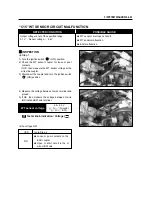
“C17” IAP SENSOR CIRCUIT MALFUNCTION
▣
▣
INSPECTION
◈
Step 1
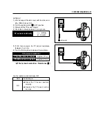
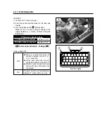
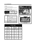
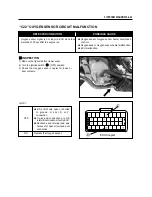
1) Lift and support the side cover with the side cover
stay. (Refer to page 2-2)
2) Turn the ignition switch “ ” (OFF) position.
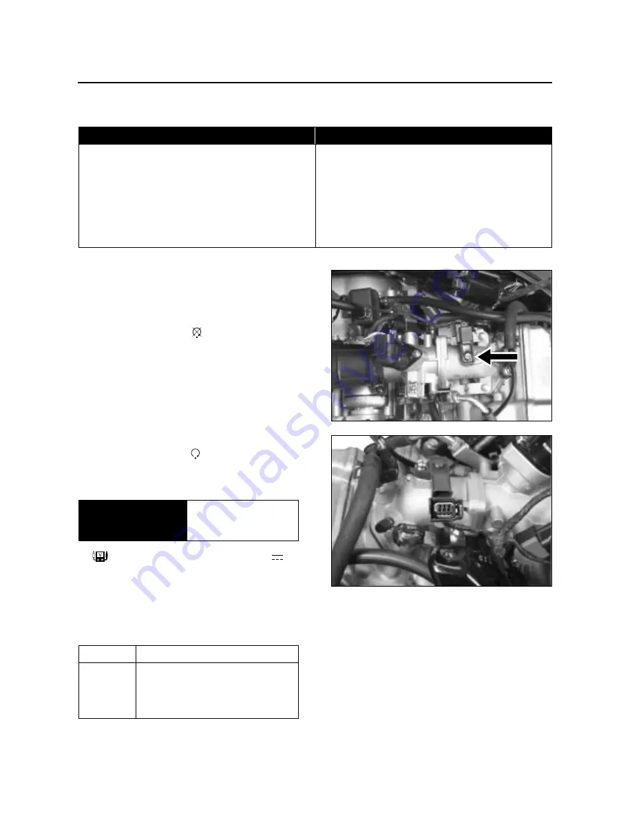
3) Check the IAP sensor coupler for loose or poor
contacts. If OK, then measure the IAP sensor
input voltage.
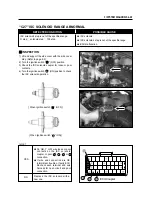
4) Disconnect the IAP sensor coupler.
5) Turn the ignition switch “ ” (ON) position.
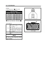
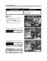
6) Measure the voltage at the OB wire and ground. If
OK, then measure the voltage at the OB wire and
BW wire.
DETECTED CONDITION
IAP sensor voltage is out of the specified range.
0.1 V
�
Sensor voltage
�
4.8 V
NOTE :
Note that atmospheric pressure varies depending on
weather conditions as well as altitude.
Take that into consideration when inspecting voltage.
●
Clogged vacuum passage between throttle body
and IAP sensor.
●
Air being drawn from vacuum passage between
throttle body and IAP sensor.
●
IAP sensor circuit open or shorted to ground.
●
IAP sensor malfunction.
●
ECU malfunction.
POSSIBLE CAUSE
YES
NO
Go to Step 2.
●
Loose or poor contacts on the
ECU coupler.
●
Open or short circuit in the OB
wire or BW wire.
IAP sensor input
voltage
4.5 ~ 5.5 V
(
�
OB -
�
Ground )
(
�
OB -
�
BW )
Is the voltage OK?
Tester knob indication : Voltage ( )
Summary of Contents for MS3 125
Page 6: ...NOTE Difference between photographs and actual motorcycles depends on the markets ...
Page 134: ...5 1 FUEL SYSTEM AND THROTTLE BODY FUEL SYSTEM ...
Page 139: ...FUEL SYSTEM AND THROTTLE BODY 5 6 THROTTLE BODY ...
Page 249: ...9 31 SERVICING INFORMATION WIRE AND CABLE ROUTING ...
Page 250: ...SERVICING INFORMATION 9 32 ...
Page 251: ...9 33 SERVICING INFORMATION ...
Page 252: ...SERVICING INFORMATION 9 34 ...
Page 253: ...9 35 SERVICING INFORMATION WIRING DIAGRAM ...
Page 254: ...SERVICING INFORMATION 9 36 ...
Page 257: ...Prepared by 1st Ed DEC 2007 Manual No 99000HP8810 Printed in Korea ...


