FI SYSTEM DIAGNOSIS 4-28
▣
▣
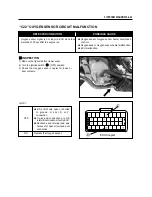
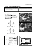
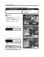
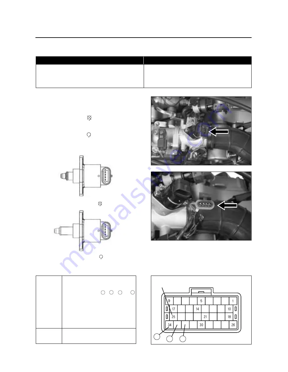
INSPECTION
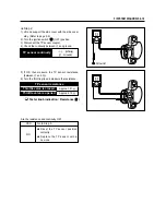
1) Lift and support the side cover with the side cover
stay. (Refer to page 2-2)
2) Turn the ignition switch “ ” (OFF) position.
3) Check the ISC solenoid coupler for loose or poor
contacts.
4) Turn the ignition switch “ ” (ON) position to check
the ISC solenoid operation.
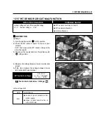
“C27” ISC SOLENOID RANGE ABNORMAL
DETECTED CONDITION
POSSIBLE CAUSE
ISC solenoid’s step is out of the specified range.
O step
�
solenoid step
�
100 step
●
ISC solenoid
●
ISC solenoid’s step is out of the specifie range.
●
ECU malfunction.
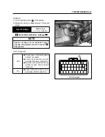
Is OK?
NO
YES
Replace the ISC solenoid with a
new one.
●
Gr, GR, Y or W wire loose or poor
contacts on the ISC solenoid
coupler, or poor
34
,
32
,
33
or
25
connection.
●
If wire and connection are OK,
intermittent trouble or faulty ECU.
Recheck each terminal and wire
harness for open circuit and poor
connection.
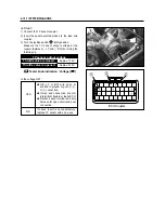
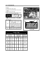
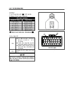
ECU Coupler
[ When Ignition switch “ ” (OFF)]
[ When Ignition switch “ ” (ON)]
�
32
33
34
Summary of Contents for MS3 125
Page 6: ...NOTE Difference between photographs and actual motorcycles depends on the markets ...
Page 134: ...5 1 FUEL SYSTEM AND THROTTLE BODY FUEL SYSTEM ...
Page 139: ...FUEL SYSTEM AND THROTTLE BODY 5 6 THROTTLE BODY ...
Page 249: ...9 31 SERVICING INFORMATION WIRE AND CABLE ROUTING ...
Page 250: ...SERVICING INFORMATION 9 32 ...
Page 251: ...9 33 SERVICING INFORMATION ...
Page 252: ...SERVICING INFORMATION 9 34 ...
Page 253: ...9 35 SERVICING INFORMATION WIRING DIAGRAM ...
Page 254: ...SERVICING INFORMATION 9 36 ...
Page 257: ...Prepared by 1st Ed DEC 2007 Manual No 99000HP8810 Printed in Korea ...

