FI SYSTEM DIAGNOSIS 4-34
SENSORS
◉
◉
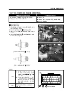
PICK-UP COIL INSPECTION
The pick-up coil
①
is installed in the magneto cover.
(Refer to page 7-6)
◉
◉
PICK-UP COIL REMOVAL AND
INSTALLATION
●
Remove the magneto cover. (Refer to page 3-7)
●
Install the magneto cover in the reverse order of
removal.
◉
◉
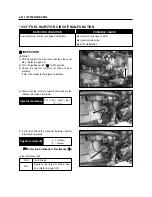
IAP SENSOR INSPECTION
The intake air pressure (IAP) sensor
②
is installed at
the upside of the intake pipe. (Refer to page 4-22)
◉
◉
IAP SENSOR REMOVAL AND
INSTALLATION
●
Lift and support the side cover with the side cover
stay. (Refer to page 2-2)
●
Remove the IAP sensor from the intake pipe.
●
Install the IAP sensor in the reverse order of
removal.
◉
◉
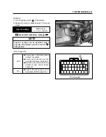
TP SENSOR INSPECTION
The throttle position (TP) sensor
③
is installed at the
left side of the throttle body. (Refer to page 4-17)
◉
◉
TP SENSOR REMOVAL AND
INSTALLATION
◉
◉
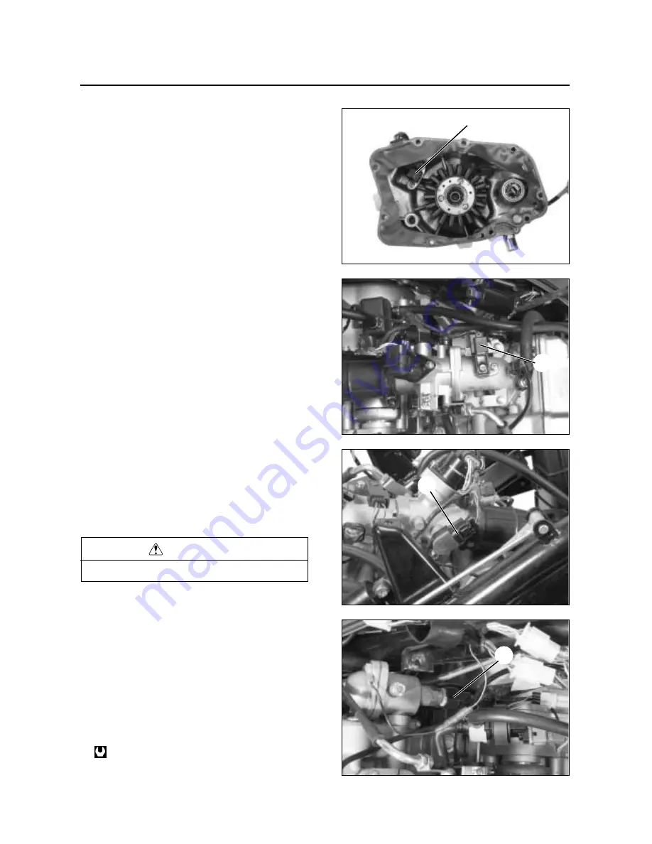
WT SENSOR INSPECTION
The water temperature (WT) sensor
④
is installed at
the rear side of the thermostat case. (Refer to page
4-20)
◉
◉
WT SENSOR REMOVAL AND
INSTALLATION
●
Remove the WT sensor. (Refer to page 6-8)
●
Install the WT sensor in the reverse order of
removal.
WT sensor : 18 N
∙
∙
m (1.8 kgf
∙
∙
m)
CAUTION
Never remove the TP sensor.
①
②
③
④
Summary of Contents for MS3 125
Page 6: ...NOTE Difference between photographs and actual motorcycles depends on the markets ...
Page 134: ...5 1 FUEL SYSTEM AND THROTTLE BODY FUEL SYSTEM ...
Page 139: ...FUEL SYSTEM AND THROTTLE BODY 5 6 THROTTLE BODY ...
Page 249: ...9 31 SERVICING INFORMATION WIRE AND CABLE ROUTING ...
Page 250: ...SERVICING INFORMATION 9 32 ...
Page 251: ...9 33 SERVICING INFORMATION ...
Page 252: ...SERVICING INFORMATION 9 34 ...
Page 253: ...9 35 SERVICING INFORMATION WIRING DIAGRAM ...
Page 254: ...SERVICING INFORMATION 9 36 ...
Page 257: ...Prepared by 1st Ed DEC 2007 Manual No 99000HP8810 Printed in Korea ...

