5-3 FUEL SYSTEM AND THROTTLE BODY
●
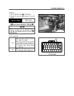
Remove the fuel tank forward.
●
Remove the fuel pump assembly
①
by removing
its mounting bolts diagonally.
●
Remove the fuel gauge
②
.
REASSEMBLY AND INSTALLATION
Reassembly and installation the fuel tank in the
reverse order of remval and disassembly.
●
When installing the fuel pump assembly, first
tighten all the fuel pump assembly mounting bolts
lightly in diagonal stages, and then tighten them
in the above tightening order.
CAUTION
As gasoline leakage may occur in this operation,
keep away from fire and sparks.
WARNING
�
�
Gasoline is highly flammable and explosive.
�
�
Keep heat, spark and flame away.
●
Tighten the fuel tank mounting bolts to the
specified torque.
●
Tighten the fuel tank guide bolts.
NOTE
Apply a small quantity of the THREAD LOCK
“1324” to the thread portion of the fuel pump
mounting bolt.
THREAD LOCK “1324”
Fuel tank mounting bolt
: 8 ~ 12 N
∙
∙
m (0.8 ~ 1.2 kgf
∙
∙
m)
①
②
Summary of Contents for MS3 125
Page 6: ...NOTE Difference between photographs and actual motorcycles depends on the markets ...
Page 134: ...5 1 FUEL SYSTEM AND THROTTLE BODY FUEL SYSTEM ...
Page 139: ...FUEL SYSTEM AND THROTTLE BODY 5 6 THROTTLE BODY ...
Page 249: ...9 31 SERVICING INFORMATION WIRE AND CABLE ROUTING ...
Page 250: ...SERVICING INFORMATION 9 32 ...
Page 251: ...9 33 SERVICING INFORMATION ...
Page 252: ...SERVICING INFORMATION 9 34 ...
Page 253: ...9 35 SERVICING INFORMATION WIRING DIAGRAM ...
Page 254: ...SERVICING INFORMATION 9 36 ...
Page 257: ...Prepared by 1st Ed DEC 2007 Manual No 99000HP8810 Printed in Korea ...

