6-5 COOLING SYSTEM
The voltmeter is for making sure that the battery
applies 12 volts to the motor. With the motor with
electric motor fan running at full speed, the ammeter
should be indicating not more than 5 amperes.
If the fan motor does not turn, replace the motor
assembly with a new one.
◉
◉
REMOVAL
●
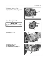
Drain engine coolant. (Refer to page 2-16)
●
Remove the front leg shield and leg shield cover.
(Refer to page 8-3 ~ 6)
●
Remove the radiator. (Refer to page 6-3)
●
Disconnect the cooling fan thermo-switch
②
.
●
Remove the cooling fan.
●
Install the radiator.
●
Route the radiator hoses properly.
●
Pour engine coolant. (Refer to page 2-16)
●
Bleed air from the cooling circuit.
(Refer to page 2-17)
●
Install the front leg shield and leg shield cover.
◉
◉
INSTALLATION
●
Install the cooling fan to the radiator.
COOLING FAN
◉
◉
INSPECTION
●
Remove the front leg shield and leg shield cover.
(Refer to page 8-3 ~ 6)
●
Disconnect the cooling fan motor lead wire cou-
pler
①
and its thermo-switch lead wire coupler.
Test the cooling fan motor for load current with an
ammeter connected as shown in the illustration.
NOTE
When making above test, it is not necessary to
remove the cooling fan.
Fan motor
Ammeter
Battery
B
BrW
Cooling fan mounting bolt
: 8 ~ 12 N
∙
∙
m (0.8 ~ 1.2 kgf
∙
∙
m)
Cooling fan motor mounting bolt
: 8 N
∙
∙
m (0.8 kgf
∙
∙
m)
①
②
Summary of Contents for MS3 125
Page 6: ...NOTE Difference between photographs and actual motorcycles depends on the markets ...
Page 134: ...5 1 FUEL SYSTEM AND THROTTLE BODY FUEL SYSTEM ...
Page 139: ...FUEL SYSTEM AND THROTTLE BODY 5 6 THROTTLE BODY ...
Page 249: ...9 31 SERVICING INFORMATION WIRE AND CABLE ROUTING ...
Page 250: ...SERVICING INFORMATION 9 32 ...
Page 251: ...9 33 SERVICING INFORMATION ...
Page 252: ...SERVICING INFORMATION 9 34 ...
Page 253: ...9 35 SERVICING INFORMATION WIRING DIAGRAM ...
Page 254: ...SERVICING INFORMATION 9 36 ...
Page 257: ...Prepared by 1st Ed DEC 2007 Manual No 99000HP8810 Printed in Korea ...


