CHASSIS 8-24
●
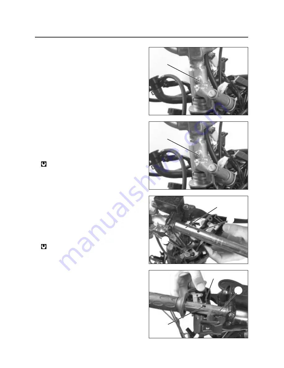
Remove the handlebar by removing the handlebar
set bolt
①
.
◉
◉
REASSEMBLY
Reassemble the handlebars in the reverse order of
removal.
Pay attention to the following points :
●
Tighten the handlebar set bolt
①
to the specified
torque.
●
With the stopper
②
engaged with the handlebar
hole
③
, assemble the handle switch.
●
When remounting the brake master cylinder onto
the handlebars, align the brake master cylinder
holder’s mating surface with punch mark
④
on the
handlebars.
●
Tighten the master cylinder upper bolt first tem-
porarily to provide clearance on the master cylin-
der lower side and then tighten both the bolts to
the specification.
Perform the following inspections after assembly has
been completed.
*
Brake
∙∙∙∙∙∙∙∙∙∙∙
Refer to page 2-18
*
Throttle operation and cable play
∙∙∙∙∙∙∙∙∙∙∙∙∙∙
Refer to page 2-11
Handlebar set bolt
: 40 ~ 50 N
∙
∙
m (4.0 ~ 5.0 kgf
∙
∙
m)
Master cylinder mounting bolt :
: 8 ~ 12 N
∙
∙
m (0.8 ~ 1.2 kgf
∙
∙
m)
①
①
④
③
②
②
④
③
Summary of Contents for MS3 125
Page 6: ...NOTE Difference between photographs and actual motorcycles depends on the markets ...
Page 134: ...5 1 FUEL SYSTEM AND THROTTLE BODY FUEL SYSTEM ...
Page 139: ...FUEL SYSTEM AND THROTTLE BODY 5 6 THROTTLE BODY ...
Page 249: ...9 31 SERVICING INFORMATION WIRE AND CABLE ROUTING ...
Page 250: ...SERVICING INFORMATION 9 32 ...
Page 251: ...9 33 SERVICING INFORMATION ...
Page 252: ...SERVICING INFORMATION 9 34 ...
Page 253: ...9 35 SERVICING INFORMATION WIRING DIAGRAM ...
Page 254: ...SERVICING INFORMATION 9 36 ...
Page 257: ...Prepared by 1st Ed DEC 2007 Manual No 99000HP8810 Printed in Korea ...


