SERVICING INFORMATION 9-2
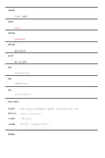
C24
C27
C32
C37
C41
C43
Ignition coil (IG coil)
Idle speed control
solenoid (ISC solenoid)
Fuel injector
Secondary air valve
solenoid (SAV solenoid)
Fuel pump relay
Oxygen sensor heater
(O
2
S heater)
Ignition coil, wiring / coupler connection, power supply from the
battery.
The idle speed control solenoid step should be the following.
O step
�
solenoid step
�
100 step
Without the above range, C27 is indicated.
Idle speed control solenoid, lead wire / coupler connection.
The fuel injector not comes in voltage from the battery, C32 is
indicated.
Injector, wiring / coupler connection, power supply to the injec-
tor.
When the IC of the ECU electric current gets 6A and more, C24
is indicated.
When the secondary air valve solenoid voltage is not input in
ECU, C37 is indicated.
Secondary air valve solenoid, lead wire / coupler connection.
Fuel pump relay, connecting lead wire, power source to fuel
pump relay, fuel injector.
No voltage is applied to the injector for 3 sec. after the contact
of fuel pump relay is turned “ON” position. Or voltage is applied
to the injector, when the contact of fuel pump is “OFF” position.
The oxygen sensor heater signal is not input in ECU.
Oxygen sensor heater, lead wire / coupler connection.
DETECTED ITEM
DETECTED FAILURE CONDITION
CHECK FOR
MALFUNCTION
CODE
Summary of Contents for MS3 125
Page 6: ...NOTE Difference between photographs and actual motorcycles depends on the markets ...
Page 134: ...5 1 FUEL SYSTEM AND THROTTLE BODY FUEL SYSTEM ...
Page 139: ...FUEL SYSTEM AND THROTTLE BODY 5 6 THROTTLE BODY ...
Page 249: ...9 31 SERVICING INFORMATION WIRE AND CABLE ROUTING ...
Page 250: ...SERVICING INFORMATION 9 32 ...
Page 251: ...9 33 SERVICING INFORMATION ...
Page 252: ...SERVICING INFORMATION 9 34 ...
Page 253: ...9 35 SERVICING INFORMATION WIRING DIAGRAM ...
Page 254: ...SERVICING INFORMATION 9 36 ...
Page 257: ...Prepared by 1st Ed DEC 2007 Manual No 99000HP8810 Printed in Korea ...


