ENGINE 3-44
●
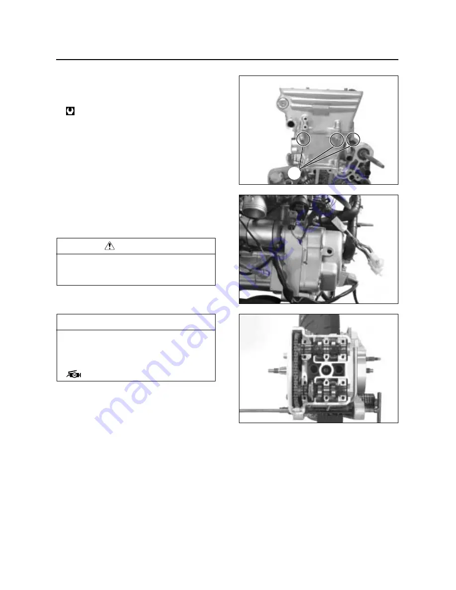
After tightening the cylinder head bolts to the
specification, tighten the cylinder head base nuts
①
to the specified torque.
CAUTION
If the crankshaft is turned without drawing the
cam chain upward, the cam chain will catch
between crankcase and cam chain sprocket.
Cylinder head base nut
: 7 ~ 11 N
∙
∙
m (0.7 ~ 1.1 kgf
∙
∙
m)
●
Place each camshaft into the correct position.
NOTE
Just before installing the camshaft into the cylin-
der head, apply MOLY PASTE to the camshaft
journals and cam faces. Also, apply engine oil to
the camshaft housing.
MOLY PASTE
●
With the “-” line on the magneto rotor is aligned with the triangle mark on the magneto cover, hold the camshaft
steady and lightly pull up the cam chain to remove any slack between the cam chain sprocket and exhaust
camshaft sprocket.
●
The exhaust camshaft sprocket has an arrow marked “1”
①
. Turn the exhaust camshaft so that the arrow is
aligned with the gasket surface of the cylinder head. Engage the cam chain with the exhaust camshaft sprocket.
●
The other arrow marked “2”
②
should now be pointing straight up. Starting from the roller pin that is directly
above the arrow marked “2”
②
, count out 16 roller pins (from the exhaust camshaft side going towards the
intake camshaft side).
Engage the 16th roller pin on the cam chain with the arrow marked “3”
③
on the intake sprocket. Refer to the
following illustrations.
①
◉
◉
CAMSHAFT ASSEMBLY
●
Turn the crankshaft until the “-” line on the mag-
neto rotor is aligned with the triangle mark on the
magneto cover.
Summary of Contents for MS3 125
Page 6: ...NOTE Difference between photographs and actual motorcycles depends on the markets ...
Page 134: ...5 1 FUEL SYSTEM AND THROTTLE BODY FUEL SYSTEM ...
Page 139: ...FUEL SYSTEM AND THROTTLE BODY 5 6 THROTTLE BODY ...
Page 249: ...9 31 SERVICING INFORMATION WIRE AND CABLE ROUTING ...
Page 250: ...SERVICING INFORMATION 9 32 ...
Page 251: ...9 33 SERVICING INFORMATION ...
Page 252: ...SERVICING INFORMATION 9 34 ...
Page 253: ...9 35 SERVICING INFORMATION WIRING DIAGRAM ...
Page 254: ...SERVICING INFORMATION 9 36 ...
Page 257: ...Prepared by 1st Ed DEC 2007 Manual No 99000HP8810 Printed in Korea ...


