1X1
INSTALLATION
3-12
HySpeed HT2000LHF
Instruction Manual
6
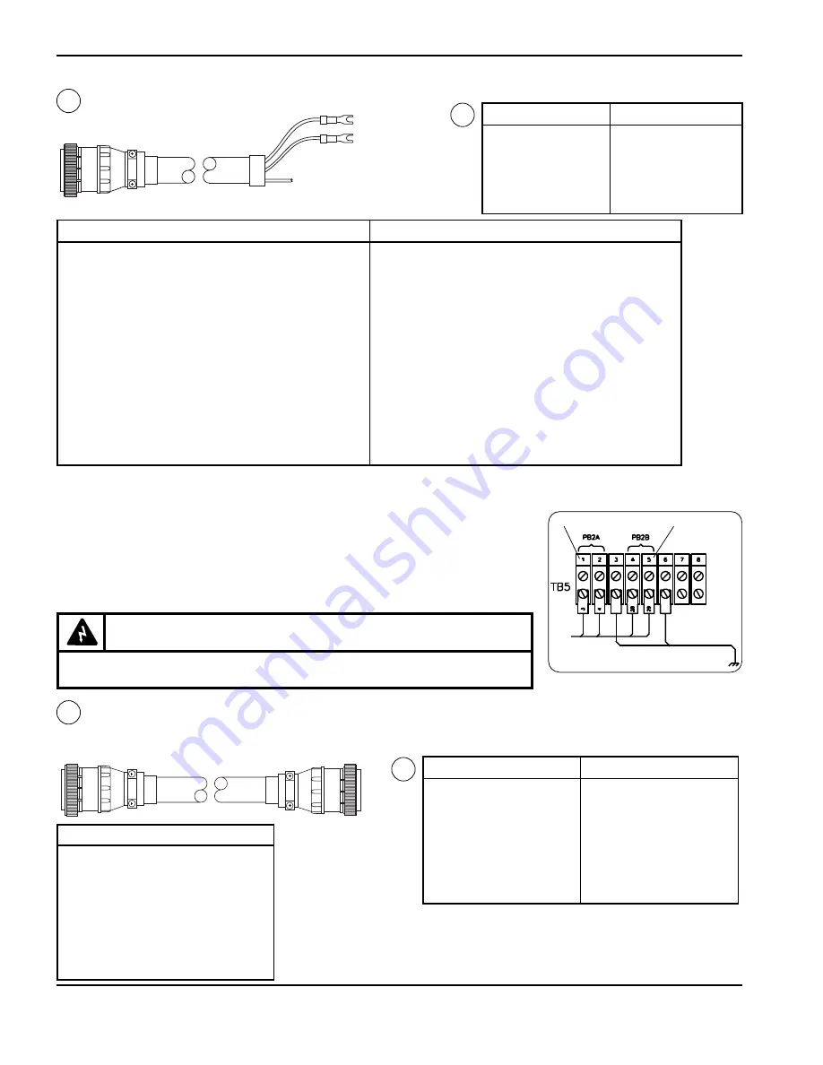
Note: If you are using a machine computer interface to set voltage and current and do not want the programmable
voltage current readout, skip references 7-9.
Remote Voltage and Current Cable – Power Supply to Digital Remote or Programmable Remote
1x4
5x1
Color
Signal
4
1
Green
SID Data
8
2
Black
SID Common
13
Grn/Blk
Shield
9
3
Red
SOD Data
15
6
Black
SOD Common
14
Red/Blk
Shield
35
7
White
AC Power
36
8
Black
AC Power
31
Wht/Blk
Shield
5
Key
22
Key
6
6
Notes: •
If using this Remote I/O Cable, remove jumpers from power supply
TB5 terminals 1&2 and 4&5 and terminate Remote I/O Cable wires for
PB2A and PB2B to a normally closed switch.
• Terminate wires for PB1A and PB1B to a normally open switch.
• Input requirements for interlocks: DC current between 15 and 20 mA; DC
voltage between 12 and 15 V.
• Refer also to pages 3 and 6 of the wiring diagrams in Section 7.
Remove jumper
Remove jumper
7
7
1X4
5X1
Part No.
Length
123294
6 ft (1.8 m)
123295
15 ft (4.6 m)
123296
25 ft (7.6 m)
123297
35 ft (10.7 m)
123298
50 ft (15.3 m)
123299
60 ft (18.3 m)
123300
75 ft (23 m)
Part No.
Length
123301
85 ft (25.9 m)
123302 100 ft (30.5)
123303 115 ft (35.1 m)
123304 120 ft (36.6 m)
123305 125 ft (38.1 m)
123306 150 ft (46 m)
123307 200 ft (62 m)
Remote I/O Cable – Power Supply to Remote Interface
1x1
Color
Signal
19
White
FS1 Interlock
20
Red
FS1 Interlock
13
Shield
Ground
23
Blue
LT1 120 VAC
24
Black
LT1 120 VAC
25
Shield
Ground
26
Red
PB2A 24 VAC
27
Green
PB2A 24 VAC
28
Shield
Ground
29
White
PB2B 120 VAC
30
Black
PB2B 120 VAC
34
Shield
Ground
32
Brown
PB1A 24 VAC
33
Black
PB1A 24 VAC
37
Shield
Ground
35
Red
PB1B 120 VAC
36
Brown
PB1B 120 VAC
31
Shield
Ground
1x1
Color
Signal
2
Yellow
PB1 LT1 24VAC
3
Black
PB1 LT1 24VAC
7
Shield
Ground
5
Orange
TS1 Interlock
6
Black
TS1 Interlock
1
Shield
Ground
8
Red
LS1 Interlock
9
Black
LS1 Interlock
4
Shield
Ground
11
Green
PS3 Interlock
12
Black
PS3 Interlock
18
Shield
Ground
14
Red
PS1,PS2 Interlock
15
Blue
PS1,PS2 Interlock
21
Shield
Ground
16
Red
TS2 Interlock
17
Yellow
TS2 Interlock
10
Shield
Ground
Part No.
Length
023990
7 ft (2.1 m)
023911
15 ft (4.6 m)
023878
25 ft (7.6 m)
023879
50 ft (15.3 m)
123040
60 ft (18.3 m)
023880
75 ft (22.9 m)
123073
85 ft (25.9 m)
023881
100 ft (30.5 m)
Part No.
Length
123188
120 ft (36.6 m)
023882
125 ft (38.1 m)
023883
150 ft (45.8 m)
023884
200 ft (61 m)
023885
250 ft (76.3 m)
023886
275 ft (83.9 m)
023887
300 ft (91.5 m)
WARNING
• Be certain to properly terminate 120 VAC wire connections!
• Provide proper strain relief for remote I/O cable at customer interface.
Summary of Contents for HT2000LHF
Page 1: ...200 Volt Plasma Arc Cutting System Instruction Manual 803040 Revision 7 HySpeed HT2000LHF ...
Page 5: ......
Page 15: ...TABLE OF CONTENTS viii Hyspeed HT2000LHF Instruction Manual 6 ...
Page 109: ...MAINTENANCE 5 20 HySpeed HT2000LHF Instruction Manual 7 ...
Page 133: ......
Page 134: ...7 5 7 Figure 7 1 HT2000LHF Coolant Flow Diagram ...
Page 135: ......
Page 136: ...7 7 7 ...
Page 137: ......
Page 138: ...7 9 7 ...
Page 139: ......
Page 140: ...7 11 7 ...
Page 141: ......
Page 142: ...7 13 7 ...
Page 143: ......
Page 144: ...7 15 7 ...
Page 145: ......
Page 146: ...7 17 7 ...
Page 147: ......
Page 148: ...7 19 7 ...
Page 149: ......
Page 150: ...7 21 7 ...
Page 151: ......
Page 152: ...7 23 7 ...
Page 153: ......
Page 154: ...7 25 7 ...
Page 155: ......
Page 157: ......
Page 159: ......
Page 174: ...APPENDIX A ARGON HYDROGEN CUTTING AND GOUGING a 14 HySpeed HT2000LHF Instruction Manual 6 ...
Page 176: ...b 2 ...
Page 177: ...b 3 ...
Page 178: ...b 4 ...
Page 179: ...b 5 ...
Page 181: ...b 7 ...
Page 182: ...b 8 ...
Page 183: ...b 9 ...
Page 184: ...b 10 ...
Page 194: ...APPENDIX E AIR FILTERS e 2 Hyspeed HT2000LHF Instruction Manual 6 ...
Page 196: ...APPENDIX F AERATION MANIFOLD FOR CUTTING ALUMINUM f 2 Hyspeed HT2000LHF Instruction Manual 6 ...
Page 198: ...APPENDIX G IEC SYMBOLS g 2 Hyspeed HT2000LHF Instruction Manual 6 ...


