background image

MAINTENANCE

3-2

powermax1650

Service Manual

0

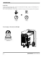
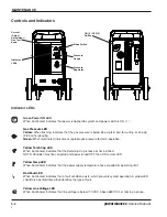
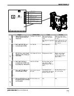
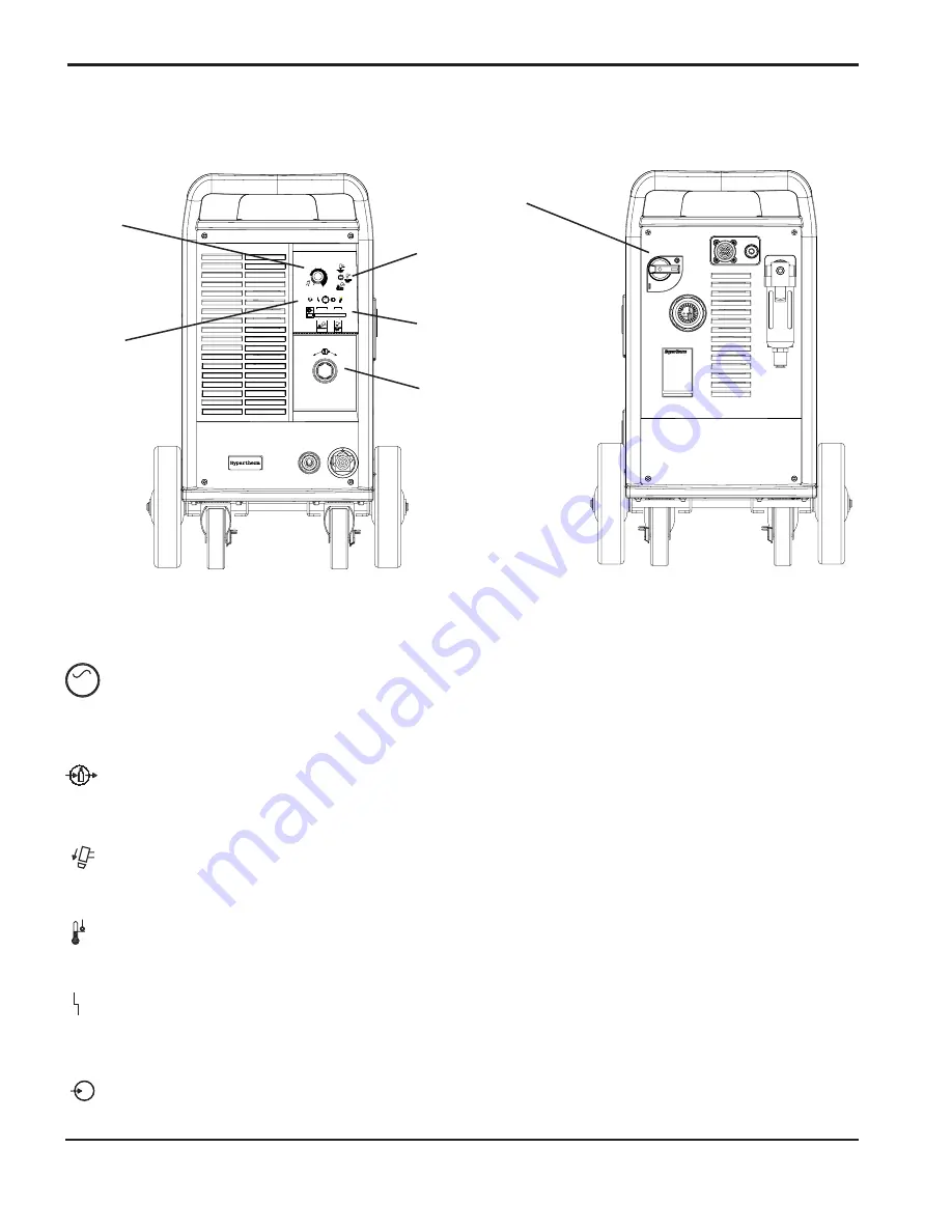
Controls and Indicators

_

+

4.0

5.0

50

60

AC

70

80

V

BAR

6.0

PSI

AMPS

30

40

100

80

60

Current
(Amps)
Adjustment /
Gas Test
Knob

Mode Switch

Indicator
LEDs

Pressure
Gauge

Pressure
Regulator

ON (I) / OFF (0)
Switch

Green Power ON LED
When illuminated, indicates that power is applied to system and power switch is ON ( I ). 

Gas Pressure LED
Yellow: 

When flashing, indicates that the gas pressure is below 65 psig (4.5 bar) for cutting, or 40 psig

(2.8 bar) for gouging.

Green: 

When illuminated, indicates acceptable gas pressure for torch operation.

Yellow Torch Cap LED

When illuminated, indicates that the Retaining Cap is loose or not installed.
NOTE: Condition must be corrected and power turned OFF then ON to clear LED.

Yellow Temp LED

When illuminated, indicates that the power supply temperature has exceeded its operating limit.

Red Fault LED

When illuminated, indicates that a fault condition exists, which prevents system operation. A yellow LED
should also be illuminated that identifies the type of fault.

Yellow Line Voltage LED

When illuminated, indicates that line voltage is below 170 VAC, above 680 VAC, or missing a phase.

AC

V

Indicator LEDs

Summary of Contents for Powermax 1650

Page 1: ...SERIES G3 _ 4 0 5 0 50 60 AC 70 80 V BAR 6 0 PSI AMPS 30 40 100 80 60 Plasma Arc Cutting System Service Manual 804470 Revision 2 ...

Page 2: ...n 2 June 2003 Hypertherm Inc Hanover NH USA www hypertherm com Copyright 2003 Hypertherm Inc All Rights Reserved Hypertherm and Powermax are trademarks of Hypertherm Inc and may be registered in the United States and or other countries ...

Page 3: ...blic of Singapore 65 6 841 2489 Tel 65 6 841 2490 Fax 65 6 841 2489 Technical Service Hypertherm UK Ltd 9 Berkeley Court Manor Park Runcorn Cheshire England WA7 1TQ 44 1928 579 074 Tel 44 1928 579 604 Fax France 15 Impasse des Rosiers 95610 Eragny France 00 800 3324 9737 Tel 00 800 4973 7329 Fax Hypertherm S r l Via Torino 2 20123 Milano Italia 39 02 725 46 312 Tel 39 02 725 46 400 Fax 39 02 725 4...

Page 4: ...nnection to the workpiece but in some countries where direct connection is not permitted the bonding should be achieved by suitable capacitances selected according to national regulations Note The cutting circuit may or may not be earthed for safety reasons Changing the earthing arrangements should only be au thorized by a person who is competent to assess whether the changes will increase the ris...

Page 5: ...herm PATENT INDEMNITY Except only in cases of products not manufactured by Hypertherm or manufactured by a person other than Hypertherm not in strict conformity with Hypertherm s specifications and in cases of designs processes formulae or combinations not developed or purported to be developed by Hypertherm Hypertherm will defend or settle at its own expense any suit or proceeding brought against...

Page 6: ...2 Le coupage peut provoquer un incendie ou une explosion 1a 2 Prévention des incendies Prévention des explosions 1a 2 Risque d explosion argon hydrogène et méthane 1a 2 Détonation de l hydrogène lors du coupage de l aluminium 1a 2 Les chocs électriques peuvent être fatals 1a 3 Prévention des chocs électriques 1a 3 Le coupage peut produire des vapeurs toxiques 1a 3 L arc plasma peut provoquer des b...

Page 7: ...xternal 3 5 Visual Inspection Internal 3 6 Resistance Checks 3 7 Troubleshooting Guide 3 9 Voltage Checks 3 14 Component Replacement 3 20 Power Cord Replacement 3 20 Torch Installataion 3 21 Filter Element Replacement 3 23 Work Cable Replacement 3 24 Capacitor Replacement 3 25 Heat Sink Component Replacement 3 26 Section 4 Parts Power Supply Exterior 4 2 Interior Right Side 4 3 Back Interior Right...

Page 8: ...n Kill 1 3 Cutting Can Produce Toxic Fumes 1 3 A Plasma Arc Can Cause Injury and Burns 1 4 Arc Rays Can Burn Eyes and Skin 1 4 Grounding Safety 1 4 Compressed Gas Equipment Safety 1 5 Gas Cylinders Can Explode If Damaged 1 5 Noise Can Damage Hearing 1 5 Pacemaker and Hearing Aid Operation 1 5 A Plasma Arc Can Damage Frozen Pipes 1 5 Additional Safety Information 1 5 Warning Label 1 6 ...

Page 9: ... sure the area is safe before doing any cutting Keep a fire extinguisher nearby Remove all flammables within 35 feet 10 m of the cutting area Quench hot metal or allow it to cool before handling or before letting it touch combustible materials Never cut containers with potentially flammable materials inside they must be emptied and properly cleaned first Ventilate potentially flammable atmospheres...

Page 10: ... on the workbench with the work cable attached during the cutting process Before checking cleaning or changing torch parts disconnect the main power or unplug the power supply Never bypass or shortcut the safety interlocks Before removing any power supply or system enclosure cover disconnect electrical input power Wait 5 minutes after disconnecting the main power to allow capacitors to discharge N...

Page 11: ...rdant clothing to cover all exposed areas Cuffless trousers to prevent entry of sparks and slag Remove any combustibles such as a butane lighter or matches from your pockets before cutting Cutting Area Prepare the cutting area to reduce reflection and transmission of ultraviolet light Paint walls and other surfaces with dark colors to reduce reflection Use protective screens or barriers to protect...

Page 12: ...s possible to the work cable Do not wrap or drape the torch lead or work cable around your body Keep as far away from the power supply as possible PACEMAKER AND HEARING AID OPERATION ADDITIONAL SAFETY INFORMATION 1 ANSI Standard Z49 1 Safety in Welding and Cutting American Welding Society 550 LeJeune Road P O Box 351020 Miami FL 33135 2 ANSI Standard Z49 2 Fire Prevention in the Use of Cutting and...

Page 13: ... path 2 3 Wear complete body protection 3 Electric shock from torch or wiring can kill Protect yourself from electric shock 3 1 Wear insulating gloves Do not wear wet or damaged gloves 3 2 Insulate yourself from work and ground 3 3 Disconnect input plug or power before working on machine 4 Breathing cutting fumes can be hazardous to your health 4 1 Keep your head out of the fumes 4 2 Use forced ve...

Page 14: ...vention des chocs électriques 1a 3 Le coupage peut produire des vapeurs toxiques 1a 3 L arc plasma peut provoquer des blessures ou des brûlures 1a 4 Torches à allumage instantané 1a 4 Les rayons de l arc peuvent brûler les yeux et la peau 1a 4 Protection des yeux Protection de la peau Zone de coupage 1a 4 Mise à la masse et à la terre 1a 4 Câble de retour Table de travail Alimentation 1a 4 Sécurit...

Page 15: ...e sont pas suivies correctement Prévention des incendies Avant de commencer s assurer que la zone de coupage ne présente aucun danger Conserver un extincteur à proximité Éloigner toute matière inflammable à une distance d au moins 10 m du poste de coupage Tremper le métal chaud ou le laisser refroidir avant de le manipuler ou avant de le mettre en contact avec des matériaux combustibles Ne jamais ...

Page 16: ...lors du coupage Laisser la pièce à couper en place ou sur la table de travail le câble de retour connecté lors du coupage Avant de vérifier de nettoyer ou de remplacer les pièces de la torche couper l alimentation ou débrancher la prise de courant Ne jamais contourner ou court circuiter les verrouillages de sécurité Avant d enlever le capot du système ou de la source de courant couper l alimentati...

Page 17: ...sées du corps Pantalon sans revers pour éviter que des étincelles ou des scories puissent s y loger Avant le coupage retirer de ses poches tout objet combustible comme les briquets au butane ou les allumettes Zone de coupage Préparer la zone de coupage afin de réduire la réverbération et la transmission de la lumière ultraviolette Peindre les murs et autres surfaces de couleur sombre pour réduire ...

Page 18: ...e jamais exposer des bouteilles à une chaleur excessive aux étincelles aux scories ou aux flammes nues Ne jamais utiliser des marteaux des clés ou d autres outils pour débloquer le robinet des bouteilles Une exposition prolongée au bruit du coupage ou du gougeage peut provoquer des problèmes auditifs Utiliser un casque de protection homologué lors de l utilisation du système plasma Prévenir les pe...

Page 19: ...tre fatal Se protéger contre les risques de chocs électriques 3 1 Porter des gants isolants Ne pas porter de gants mouillés ou abîmés 3 2 S isoler de la surface de travail et du sol 3 3 Débrancher la prise ou la source de courant avant de manipuler l équipement 4 L inhalation des vapeurs produites par le coupage peut être dangereuse pour la santé 4 1 Garder le visage à l écart des vapeurs 4 2 Util...

Page 20: ...ion 2 SPECIFICATIONS In this section Specifications Power Supply 2 2 Power Connection 2 3 Engine Drives 2 3 Duty Cycle 2 4 Power Supply Dimensions and Weight 2 4 Specifications T100 Torches 2 5 Torch Dimensions 2 6 Symbols and Markings 2 7 ...

Page 21: ...VAC 3PH 21 19 U1 Volts AC rms Harmonic Displacement Power Factor Power Factor Power Factor 200 208 VAC 3PH 0 94 0 98 230 240 VAC 3PH 0 94 0 98 380 415 VAC 3PH 0 94 0 99 480 VAC 3PH 0 94 0 99 600 VAC 3PH 0 78 0 99 Rsce Short Circuit Ratio CE Model only U1 Volts AC rms 3PH Rsce 400 VAC 191 230 VAC 142 This equipment conforms to IEC 61000 3 12 provided that Rsce min 191 at 400VAC 3PH and 142 at 230 V...

Page 22: ...errupt level of the switch must be equal to or exceed the continuous rating of the fuses Use slow blow fuses rated per local and national electrical codes Engine Drives When using an engine drive to power the Powermax1650 The engine drive must be dedicated to powering the plasma cutting system Engine drive operation 1 Set the engine drive output to 3 phase AC 2 Plug the Powermax1650 power cord int...

Page 23: ...out torch 124 lb 56 2 kg 26 4 in 671 mm 16 8 in 427 mm 25 8 in 655 mm Duty Cycle Duty cycle is the percentage of time during a 10 minute period that the power supply can cut continuously The diagram below depicts an 80 duty cycle Note Refer to Specifications Power Supply to determine the duty cycle that corresponds with the input power 8 minutes cutting 2 minutes resting ...

Page 24: ...rance capacity 1 3 4 inch 45 mm Gouging Capability 22 8 pounds 10 4 kg hour metal removal rate on mild steel Weight T100 7 2 pounds 3 3 kg with 25 ft 7 5 m lead 13 9 pounds 6 3 kg with 50 ft 15 m lead 8 3 pounds 3 8 kg with 25 ft 7 5 m lead T100M 11 0 pounds 5 0 kg with 35 ft 10 7 m lead 15 0 pounds 6 8 kg with 50 ft 15 m lead Specifications T100 Torches ...

Page 25: ...ual SPECIFICATIONS 0 Torch Dimensions T100 Hand Torch Dimensions 8 9 226 mm 4 2 107 mm 1 5 38 mm 1 00 25 mm T100M Machine Torch Dimensions 15 47 393 mm 1 00 25 mm 1 38 35 mm 2 35 60mm 8 203 mm 32 pitch 125 3 2 mm width 2 55 65 mm ...

Page 26: ... maintain S mark compliance IEC Symbols Used The following symbols may appear on the power supply data plate control labels and switches O l Direct Current DC The terminal for the external protective earth conductor AC input power connection Plasma torch cutting and gouging Alternating current AC An inverter based power source Volt amp curve drooping characteristic Power is off Power is on Plasma ...

Page 27: ...2 8 powermax1650 Service Manual SPECIFICATIONS 0 ...

Page 28: ...ng 3 5 Test Equipment 3 5 Troubleshooting Procedures and Sequence 3 5 Visual Inspection External 3 5 Visual Inspection Internal 3 6 Resistance Checks 3 7 Troubleshooting Guide 3 9 Voltage Checks 3 14 Component Replacement 3 20 Power Cord Replacement 3 20 Torch Installataion 3 21 Filter Element Replacement 3 23 Work Cable Replacement 3 24 Capacitor Replacement 3 25 Heat Sink Component Replacement 3...

Page 29: ...gouging Green When illuminated indicates acceptable gas pressure for torch operation Yellow Torch Cap LED When illuminated indicates that the Retaining Cap is loose or not installed NOTE Condition must be corrected and power turned OFF then ON to clear LED Yellow Temp LED When illuminated indicates that the power supply temperature has exceeded its operating limit Red Fault LED When illuminated in...

Page 30: ...540 VAC the bus voltage will rise to Vin 2 The inverter consists of an IGBT Q13 the power transformer T2 a current sense transformer and sections of the power board The inverter operates as a pulse width modulator controlled bridge circuit and is rectified by the output diode The output circuitry consists of 2 current transfer sensors located on the power board the pilot arc IGBT Q15 and the outpu...

Page 31: ...ozzle and electrode shorted Gas solenoid valve V1 opens Gas flow starts Torch blows back nozzle and electrode separate Pilot arc starts Position torch on work piece Depress plasma start switch on hand torch or remote start switch for machine torch Power circuits are ready Gas solenoid valve V1 closes Gas flow stops Set gas pressure see Setup section in Operator Manual Select desired cutting amps w...

Page 32: ...dures and Sequence When performing the troubleshooting procedures Refer to Section 6 for the system wiring diagram Refer to Section 4 to locate power supply components Refer to Section 5 for torch components After the problem has been located and repaired refer to the Sequence of Operation flow diagram in this section to test the power supply for proper operation Visual Inspection External 1 Inspe...

Page 33: ...ot attempt to repair the power board or control board Do not cut away or remove any protective conformal coating from either board To do so will risk a short circuit between the AC input circuit and the output circuit and may result serious injury or death HOT PARTS CAN CAUSE SEVERE BURNS Allow the power supply to cool before servicing MOVING BLADES CAN CAUSE INJURY Keep hands away from moving par...

Page 34: ...in this section isolate the problem by removing wires attached to the resistance check points or component until the problem is found After the problem has been located and repaired refer to the Sequence of Operation flow diagram in this section to test the power unit for proper operation Resistance Check 1 1 With the power disconnected set the ON OFF switch S1 to ON 2 Check resistance across inpu...

Page 35: ... 1 and 3 with an ohm meter in diode test mode Value should be open with meter leads in one direction and 0 1V to 1 0V with meter leads reversed Diode is shorted if value is less than 0 1V Replace diode Diode is open if value is greater than 1 0V in both directions Replace diode Linkage bar Note Black marker on wire to lower diodes ...

Page 36: ...were found during the initial resistance checks and the power supply still does not operate correctly see the Troubleshooting Guide on the following pages Note The Troubleshooting Guide provides most probable causes and solutions Study the system wiring diagram and understand the theory of operation before troubleshooting Before purchasing a major replacement component verify the problem with Hype...

Page 37: ...stment knob is in gas test position Turn knob clockwise until above the 25 amp setting Solenoid valve V1 stuck open Faulty valve Disconnect J20 from power board PCB2 If air flow continues replace valve V1 Defective power board PCB2 Constant voltage supplied to valve Disconnect J20 from power board PCB2 If air flow stops replace power board Incoming gas pressure is too high Incoming gas pressure is...

Page 38: ...depressed If open circuit inspect torch and lead assembly Solenoid valve not working Valve stuck or no voltage to valve Check voltage at valve Remove connector J21 from valve turn current adjust knob to test flow and check for 24 VDC at connector J21 pins 1 and 3 If no voltage replace power board If voltage clear air lines or replace valve Damaged torch or lead assembly Torch plunger stuck open or...

Page 39: ...red by the fault LED If no fault LED is illuminated replace power board Poor work lead connection Verify work lead is attached to workpiece and workpiece is free of rust paint etc Damaged work lead Check continuity of work lead Replace or repair as required Defective pilot arc IGBT Q15 Turn power OFF remove consumables check resistance between plunger and work piece If resistance is greater than 8...

Page 40: ... board PCB3 and Fault lamp are illuminated Invertor interlock No current from invertor power board PCB2 control board PCB3 or IGBTs Start and TSO LEDs on control board PCB3 Torch stuck in open position Torch plunger stuck consumables are worn or defective Pilot Arc IGBT See Resistance Check 3 in this section Start and SP LEDs on control board PCB3 and Fault lamp are illuminated LED is for future u...

Page 41: ...50 Service Manual 0 Voltage Checks Voltage Check 1 Check input voltage to the input diode bridge The AC voltage between any 2 input wires should equal the line voltage Note All values are 15 Line Voltage Line Voltage Line Voltage ...

Page 42: ...MAINTENANCE powermax1650 Service Manual 3 15 0 Voltage Check 2 Check output voltage of the input diode bridge Output VDC Line Voltage 1 414 Note All values are 15 Line Voltage 1 414 ...

Page 43: ...MAINTENANCE 3 16 powermax1650 Service Manual 0 Voltage Check 3 Check voltage across IGBT module Q14 Note All values are 15 750 VDC ...

Page 44: ...MAINTENANCE powermax1650 Service Manual 3 17 0 Voltage Check 4 Check voltage across IGBT module Q13 Note All values are 15 750 VDC 375 VDC 375 VDC ...

Page 45: ...MAINTENANCE 3 18 powermax1650 Service Manual 0 Voltage Check 5 Check voltage across power supply capacitors Note All values are 15 375 VDC ...

Page 46: ...les 2 Check resistance between Q15 and J17 with system in Gas Test mode The value should be 1 MΩ If not verify electrode and torch plunger move freely 3 Pilot arc shorted check resistance between Q15 and J17 with torch removed If value is 1 KΩ replace Pilot Arc IGBT 4 Pilot arc open use a jumper wire to jump J14 to Q15 Then attempt to fire the torch If the torch fires replace the Pilot Arc IGBT No...

Page 47: ...40 100 80 60 Plug Installation The plug must be connected to the power cord by a licensed electrician L1 10 Ground L2 6 152 mm 9 5 241 mm Route power cord through strain relief and tighten Power Switch Ground PE L1 L3 Strain relief Strain relief inserts 2 Strip and prepare the power cord wires as shown below Power Cord Installation Connect power cord to power switch Note Select the smallest strain...

Page 48: ...nual 3 21 0 Torch Installation Turn OFF power Remove power cord from power receptacle Open Easy Torch Removal ETR door and route lead through the end cap OFF ON _ 4 0 5 0 50 60 AC 70 80 V BAR 6 0 PSI AMPS 30 40 100 80 60 ETR Door End Cap ...

Page 49: ...uick release collar and insert the lead s gas fitting Slide quick release collar foward to lock the gas fitting in place Make sure that the gas fitting is secure Make sure that the red dot on the connector is on top then plug in the electrical connector Close ETR door Quick Release Collar ...

Page 50: ... hold B Rotate filter bowl until it is released C Pull filter bowl down to remove Do not discard the O ring A B C Install filter bowl A Slide filter bowl over filter element B Align marks on filter bowl and filter body C Rotate filter bowl until it locks in place Remove the filter element Part No 011092 from the filter housing NOTE Do not allow the filter element to turn when loosening the screw ...

Page 51: ... figure below 1 Install the strain relief to the power supply and secure with nut 2 Tighten the strain relief collar onto the cable 3 Connect the work cable to the power board at J14 Tighten nut to 10 in lb 12 kg cm of torque 4 Install ETR barrier 5 Install the power supply cover CAUTION This is a high current connection Proper torque is critical ETR Barrier Strain Relief Connect to J14 Work Cable...

Page 52: ...power supply Remove lower capacitor first Then the upper capacitor may be tipped down and removed Installation Refer to figure below Align bleeder hole on capacitor with view hole on power board Install new capacitor and secure with 2 screws Tighten screws to 30 inch pounds 36 kg cm Install the power supply cover Remove and install capacitors from fan side Correct orientation of bleeder hole Remov...

Page 53: ...ent install with screws and tighten to required torque Note Remix grease if material seperates Re torque after 2 minutes Repeat until torque is maintained Clean excess grease from heat sink Notes 1 Apply white thermal grease DC 340 Part no 027662 and torque to 8 in lb 9 kg cm 2 Apply white thermal grease DC 340 Part no 027662 and torque to 35 in lb 40 kg cm 3 Apply grey thermal grease TC 330 Part ...

Page 54: ...1650 Service Manual 4 1 0 Section 4 PARTS POWER SUPPLY In this section Exterior 4 2 Interior Right Side 4 3 Back Interior Right side 4 4 Interior Fan Side 4 5 Heat Sink Assembly 4 6 Recommended Spare Parts 4 7 ...

Page 55: ...anel Domestic 1 128765 Front end panel CE 1 2 008965 Current adjustment knob 1 3 110413 Control Panel Label 1 4 128735 End cap screws 4 5 123645 Ground clamp 1 6 011096 Regulator knob 1 7 128740 Power supply cover with labels Domestic 1 128762 Power supply cover with labels CE 1 8 128629 Cover screws 14 9 128742 Rear end panel 1 _ 4 0 5 0 50 60 AC 70 80 V BAR 6 0 PSI AMPS 30 40 100 80 60 ...

Page 56: ...bly Domestic PCB3 1 2 128659 Pressure Transducer 1 3 128801 Pressure Regulator 1 4 128699 Pilot Arc IGBT Gate Drive Cable 1 5 128810 ETR Box 1 6 128622 Gas Manifold V1 1 7 046116 Tubing 8mm OD 6mm ID nylon 3 ft 8 108211 On Off Knob 1 9 128665 Strain relief arc voltage 1 10 128662 Machine interface 1 11 128737 Power PCB PCB2 1 12 123602 Gate Drive Cables 3 ...

Page 57: ... Part Item number Description Designator Quantity 1 128757 Front caster 2 2 128763 Rear axel 1 3 128764 Rear wheel replacement 2 4 128706 EMI filter PCB CE only PCB1 1 5 128672 Power switch CSA S1 1 128761 Power switch CE _ 4 0 5 0 50 60 AC 70 80 V BAR 6 0 PSI AMPS 30 40 100 80 60 1 2 3 4 5 ...

Page 58: ...r Fan Side Part Item Number Description Designator Qty 1 128627 Filter bowl 1 011093 Air filter element 1 011094 O ring 1 2 128749 Inductor input choke L2 1 3 128741 Capacitor 2 4 128739 Power transformer T2 1 5 128749 Inductor output choke L1 1 6 128683 Fan subassembly M1 1 ...

Page 59: ...mal grease 5 oz DC 340 1 1 128733 Output diode bridge 1 2 128747 Snubber resister assembly 1 3 128743 IGBT inverter Q13 1 4 128744 Temperature Switch PCB4 1 5 128745 IGBT PFC Q14 1 6 128746 Input diode bridge D24 1 7 128748 IGBT pilot arc 1 8 128734 Snubber resister 1 9 129782 Snubber resister 1 Reference page 3 26 for torque specifications ...

Page 60: ...46116 Tubing 8mm OD 6mm ID nylon 4 3 108211 On Off Knob 4 3 128665 Strain relief arc voltage 4 3 128662 Machine interface 4 3 128737 Power PCB 4 3 123602 Gate Drive Cables 4 3 128757 Front Caster 4 4 128763 Rear Axel 4 4 128764 Rear Wheel 4 4 128706 EMI Filter PCB CE only 4 4 128672 Power switch 4 4 128627 Filter bowl 4 5 011093 Air filter element 4 5 011094 O ring 4 5 128749 Inductor input choke ...

Page 61: ...PARTS POWER SUPPLY 4 8 powermax1650 Service Manual 0 ...

Page 62: ...1650 Service Manual 5 1 0 Section 5 PARTS LIST TORCH AND CONSUMABLES In this section T100 Hand Torch Assembly 5 2 T100M Machine Torch Assembly 5 4 Torch Consumable Configurations 5 6 Recommended Spare Parts 5 8 ...

Page 63: ... 1 5 075571 Cap off Sensor screws 2 6 128768 T100 T100M Torch Head Repair Kit 1 7 128756 Handle Kit 1 8 075586 Handle screws 5 9 002244 Safety Trigger 1 10 027254 Trigger Spring 1 11 128755 25 ft 7 6 m Torch Lead Replacement Kit 1 12 128752 50 ft 15 2 m Torch Lead Replacement Kit 1 13 128638 ETR Repair Kit Regional Repair Centers only 1 14 128642 Start Switch Replacement Kit 1 Top assembly include...

Page 64: ...PARTS TORCH AND CONSUMABLES powermax1650 Service Manual 5 3 0 ...

Page 65: ...71 Cap off Sensor Screws 2 6 128768 T100 T100M Torch Head Repair Kit 1 7 128643 Torch Mounting Sleeve Replacement Kit 1 8 075004 Torch Mounting Screws 3 9 128710 Torch Positioning Sleeve 1 10 128753 25 ft 7 6 m Torch Lead Replacement Kit 1 11 128751 35 ft 10 7 m Torch Lead Replacement Kit 1 12 128759 50 ft 15 2 m Torch Lead Replacement Kit 1 13 128638 ETR Repair Kit Regional Repair Centers only 1 ...

Page 66: ...PARTS TORCH AND CONSUMABLES powermax1650 Service Manual 5 5 0 ...

Page 67: ...ations 120929 120925 120926 120932 120928 220065 220011 220048 40A 100A O Ring 058519 120929 120931 120928 60A 120929 120927 120928 80A 220051 220037 Shield Nozzle Retaining Cap Swirl Ring Electrode 120925 120926 120977 220063 220048 100A O Ring 058519 120977 220059 120928 60A 120977 120978 120928 80A 220051 220037 ...

Page 68: ...9 220064 220048 100A 120979 220006 120928 40A O Ring 058519 120979 120980 120928 80A 120979 220007 120928 60A 220051 220037 120925 120926 Use an ohmic sensing cap when a compatible torch height contoller is installed In CE countries unshielded consumables may only be used in mechanized torch applications Maintain torch to work distance of approximately 3 16 inch 4 8 mm 220061 Shield Nozzle Retaini...

Page 69: ...ws 020620 Torch Positioning Sleeve 32 Pitch 10 Inches Rack Standard 120668 Torch Positioning Sleeve without Rack 1 3 8 Inches Diameter 075004 Torch Mounting Screws 059264 T100 Hand Torch Assembly with 25 ft 7 6 m Lead 059270 T100 Hand Torch Assembly with 50 ft 15 2 m Lead 128755 T100 Hand Torch Replacement Lead 25 ft 7 6 m 128752 T100 Hand Torch Replacement Lead 50 ft 15 2 m 059265 T100M Machine T...

Page 70: ...powermax1650 Service Manual 6 1 0 Section 6 WIRING DIAGRAMS In this section Timing Diagrams 6 2 Electrical Schematic 6 4 ...

Page 71: ...ble Inverter 0 1 3ms INV_EN Icommand 0 30A 3ms Setpoint 10 0 21 5 13ms Ipilot Amps Gas 0 1 Postflow 60 Pcritical 15 at Torch psi Gas Pressure Time x Consumable Re Seat 0 225 Voltage Arc volts 10ms typ 250 1 6 30 I Setpoint 0 amps I Work Lead 30 0sec NORMAL MODE 1ms 30 160 210 0 4 21 5A valid 3ms tdelay 0 1 If 5 0 sec pilot arc time out XFR signal Digitized in DSP and Switch Constant Machine Motion...

Page 72: ...and 0 1 21 5A Reattach transfer causes CPA OPERATION 40A 1 6A I SETPOINT 0 4A 30A 30A NOTE UNIT IS ALREADY IN TRANSFER MODE Digitized XFR signal in DSP 1ms I work lead 30A Digitized Setpoint MUST BE 10ms 2 17A ms 013353 ELEC SCHEM 100A TMG 2 OF 2 A If 10 00 sec Must be 28us 1ms ...

Page 73: ... 1 3 2 4 5 6 3B 3C 4B 4C 6B 6C 5C 5B 13 12 11 1C 1B 2B 2C 16 14 15 042188 ULN2003A U2 PREFLOW SSR PA t 60V 0 20A RT9 109024 BRIDGE D24 INPUT GND CONTROL 6 COMT 18REG 18T 6INV 18INV FLYBACK SUPPLY POWER SYSTEM T1 18PA COMPA 5 10 24 PE CKT PFC CONTROL POWER BD PCB2 SOFT START K1 K2 VacR I Vbus 1 3 2 J8 PFC IGBT Q14 C92 2 1 J6 3 2 Vbus J9 PFC CHOKE C100 J7 1 POWER TRANSFORMER 30 OHM YEL J13 YEL P2 10...

Reviews: