User manual R3
DLCP
- 21 -
4.6.5
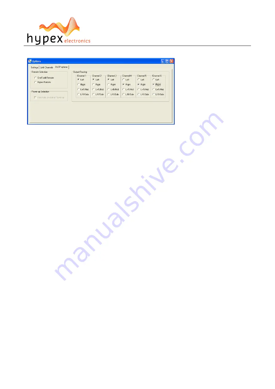
DLCP options window
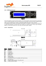
Figure 21
The DLCP options window is under Tools > Options > DLCP options
Two different IR remote codes can be used to control the DLCP control, this can be switched in the
remote selection. This information will be send to the DLCP control when present.
The DLCP can automatically turn on when power is applied without waiting for the DLCP control, if
this is desirable. See the Power-up selection function.
You can change the source for each output on the right side (Output Routing) for example: select Left
to get the left input signal of the active input, and right for the right input signal. Select L+R to add
the left and right input signal on that channel. The L-R option will subtract the input signals.
By default the output routing is set for a stereo 3-way setup:
Ch1: Left (tweeter)
Ch2: Left (woofer)
Ch3: Left (subwoofer)
Ch4: Right (tweeter)
Ch5: Right (woofer)
Ch6: Right (subwoofer)
Please note that these settings are overruled by an control board if it’s connected.
4.6.6
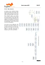
Work flow
Measuring using the DSP unit set to “flat”
Perform impulse response measurements for each driver separately. Save the entire impulse record –
truncation can be done later on the filter design program. Please use the connected amplifier which
will be used in the final setup. A different amplifier may also be used for measuring the drivers, pro-
vided the amplifier’s output impedance is as low as the final setup amp.
Importing response data
Select the tab for the channel you want to import and click “select”. The filter designer expects the
impulse response measurement as a text file with one sample per line.
There is no restriction on the absolute gain of the impulse response data. The only thing that mat-
ters is that the absolute gain be the same for all three measurements. The filter designer computes a
gain offset based on all loaded responses to centre them collectively on the vertical scale.
Truncating response data
Switch to the impulse or step response graph.

