User manual R3
DLCP
- 8 -
2.5
Add-ons
2.5.1
DLCP Input board
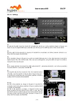
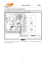
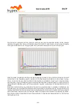
Figure 3
The DLCP can be used as a digital pre amplifier when the optional “DLCP input board” is bought. This
input board can be connected to the DLCP with only 2 flat cables. You can increase the number of
analogue inputs to 4 balanced stereo analogue inputs. It has four digital inputs; USB audio, AES
(XLR/RJ45
1
), S/PDIF and Optical in. It has two digital outputs; AES (XLR/ RJ45
1
) and S/PDIF.
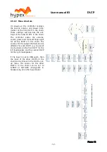
It’s possible to connect two DLCP’s with only one input board. J5/J5B can be used to connect the
third DLCP, or the second DLCP if it’s not in the same case. The control and digital outputs of the first
DLCP (connected to J2/J3) and analogue inputs are linked trough the inputs of the second DLCP
(connected to J2B/J3B). Three or more DLCP modules can be connected together with a straight
through (8-wire) cat5 cable with RJ45 connectors. The bus is specified and tested for cables up to 10
meter.
Note 1:
Switchable on PCB. See
“Settings” for information about the right positioning of the switch-
es.
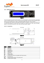
2.5.1.1
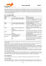
Connections
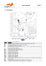
Figure 4
Name
Function
J1
Mounting block
S1
USB switch (switch between DLCP 1, J3 / DLCP 2, J3B)
J6
USB connector
J4
Control in (If this connector is used, don’t use J4B)
4)
J4B
Control in (If this connector is used, don’t use J4)
4)
J5
Control out (If this connector is used, don’t use J5B)
4)
J5B
Control out (If this connector is used, don’t use J5)
4)
J8
Digital AES/EBU input
1)
J9
Digital AES/EBU output
2)
J18
Digital optical input
J7
Digital S/PDIF in- and output
3)
(red=input, white=output)
J10
Analogue 1 left input
J11
Analogue 1 right input
J12
Analogue 2 left input
J13
Analogue 2 right input
J14
Analogue 3 left input
J15
Analogue 3 right input
J16
Analogue 4 left input
J17
Analogue 4 right input
J2
Analogue/Digital audio in and digital output header


