User manual R3
DLCP
- 9 -
J2B
Analogue/Digital audio in and digital output header for optional second DLCP
J3
I/O connector (USB, Relay, Control)
J3B
I/O connector (USB, Relay, Control) for optional second DLCP
S2
AES in select (J8 or J4)
S3
AES out select (from DLCP1, J2 / DLCP2, J2B)
S4
AES out select (output S3 to J9 or J5)
S5
Control out select (DLCP1 or DLCP2)
S6
Last select
S7
S/PDIF out select (from DLCP1 or DLCP2)
J19
For future use
J20
For future use
J21
For future use
J22
For future use
Note 1:
Set S2 in right position.
Note 2:
Set S3 and S4 in right position.
Note 3:
Set S7 in right position.
Note 3:
Set S5 and S6 in right position.
2.5.1.2
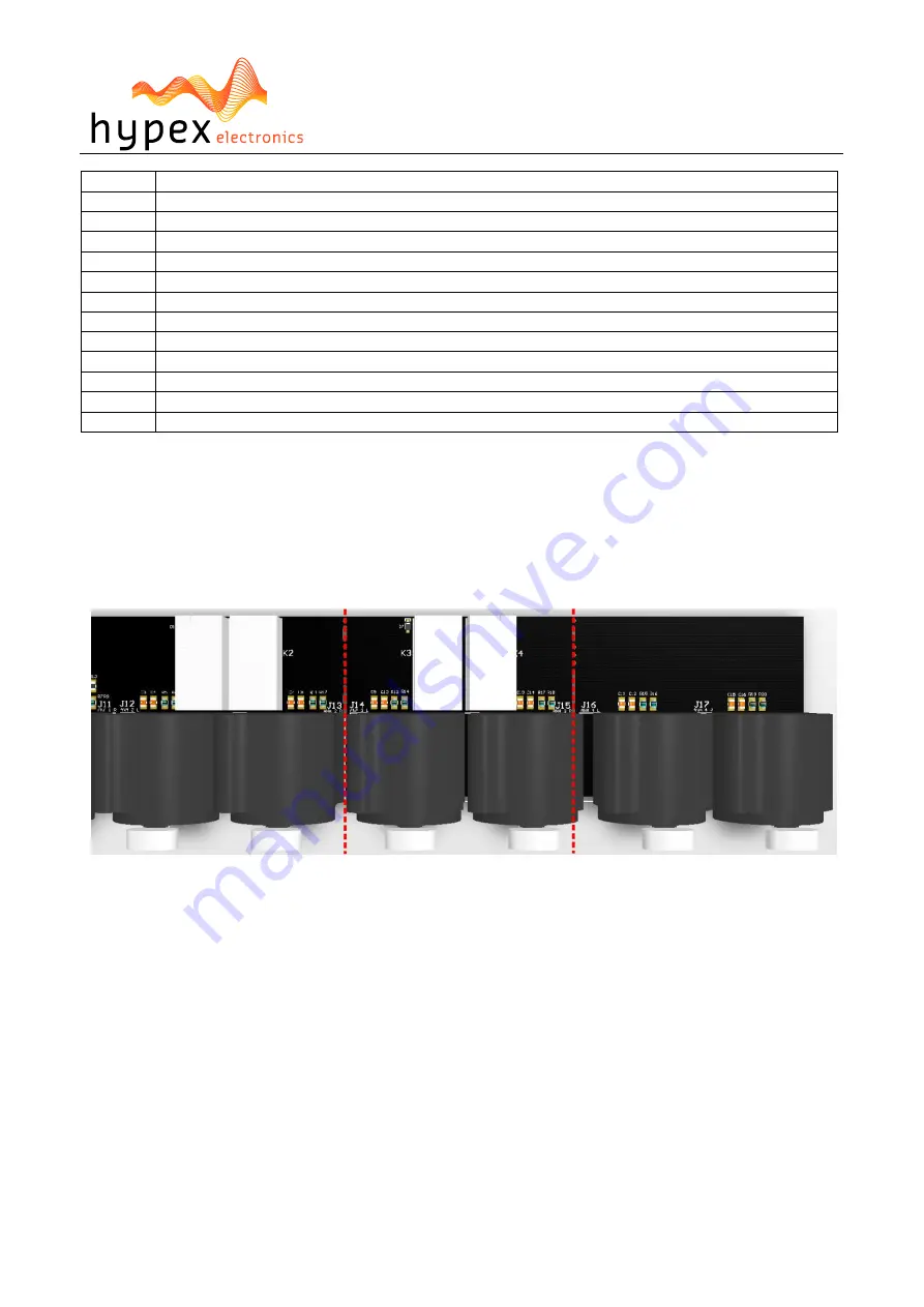
Break lines
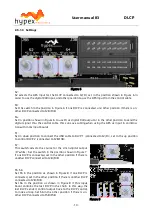
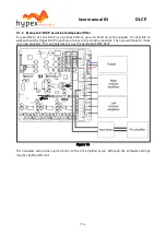
It’s possible to remove the last 1 or 2 analogue inputs to reduce the length of the input board. It’s
impossible to undo this action!
The break lines are marked with the red lines.
Figure 5


