User manual R5
PSC
2
.
400
- 7 -
rates
192
verted to 48kHz
Gain
+16
dB
volume at 0dB
Analogue Latency
1,12
ms
AES Latency
3,58
ms
* Note: Total power for the PSC2.400 is limited to 500Watts total
Hardware Architecture
The standard version of the PSC2.400 has an analogue balanced audio input. This analogue signal is
converted to digital, processed by the DSP and then converted back to analogue. A microcontroller
controls the DSP and communicates with the PC and can set the presets. An unbalanced source may
also be applied, this signal is divided over the two input DAC’s to get better performance.
Digital audio input
The digital version of the PSC2.400d comes with an AES/EBU digital audio input. Incoming AES/EBU
is linked through directly to the output and send to the DSP through an asynchronous sample rate
converter (ASRC) for jitter removal. The ASRC chip scans its input for whichever signal is active.
When the module is set to “Auto input select”, in the control panel on the computer, the input source
is automatically switched to digital when present. If the digital audio is stopped the source will be
switched back to analogue.
Controllers
The PSC2.400 can only be controlled through USB. When the module is powered on it will automati-
cally start up with the last settings. All setting, like volume and preset, are stored after a change is
made.
Clip limiter
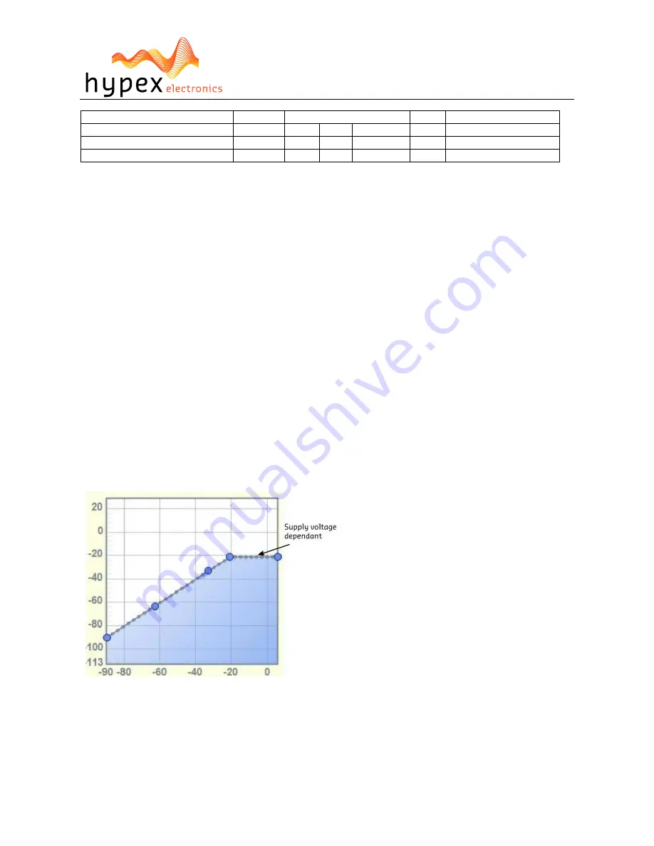
The PSC2.400 has a build in clip protection. The module measures the supply voltage and uses this
value for the limiter. Figure 5 shows the response graph of the limiter.
The hold time is fixed to 100ms and the decay is set to 100dB/s.
Figure 5
When the limiter for either channel is active the Clip led will be lit.
Thermal protection
All modules fitted with Hardware ‘PSC2 V2’ or later, delivered since November 2010, have a build-in
thermal protection. This protection lowers the output gain 1 dB per degree starting at plate tempera-
ture of 70 degrees Celsius. The outputs will be completely muted when the temperature rises over 90
degrees.


