© 2022 HyQuest Solutions
16
Installation
It is possible to use an external resistor such as a 250 Ω to raise the voltage range measured.
I.e. 100 Ω will give a working range of 0.4V to 2V, 250 Ω will give a range of 1V to 5V.
In this case, ensure the internal sink enable link is open. The resistor value in the analogue scaling calculator in
iLink will need to be changed to the value actually used. Also, a voltage measurement range for the analogue
input range needs chosen instead of current.
2.3.2.2
Analogue Output
The iRIS has a single variable analogue output. This may be configured to deliver either a voltage output ranging between
0-5V or a current output ranging from 4-20mA. The output's electrical signal (voltage or current) is link selectable. See
section
for details on configuring the analogue output.
2.3.3
Digital I/O
The iRIS has four digital I/O channels which can each be configured as either an input or output. When set as an output,
the channel can either supply switched 12V or else act as a pull-down switch for loads with a different supply voltage. If
the digital output configuration is set to 0 (Disabled) the channel is by default an input. See section
for details on configuring the digital outputs.
§
§
2.3.3.1
Digital Channels as Inputs
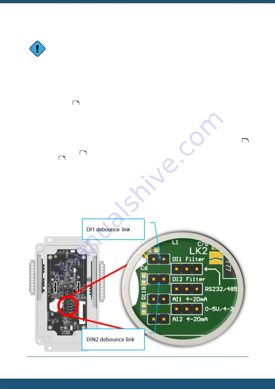
The digital inputs are selectable for either mechanical or electronic operation. In either case it is necessary to pull the input
down to 0Vdc to activate it. Inputs will handle up to 30Vdc in the off state for parallel connection across existing
equipment. The “debounce” is enabled by a jumper link, which if fitted enables a longer time constant circuit to eliminate
multiple pulses caused by contact bounce. The debounce jumpers are positioned in the centre of the PCB. The picture
below shows the links in their default positions.
Figure 7 – Digital Input Debounce Links
36
37
16
17


