© 2022 HyQuest Solutions
73
Configuration
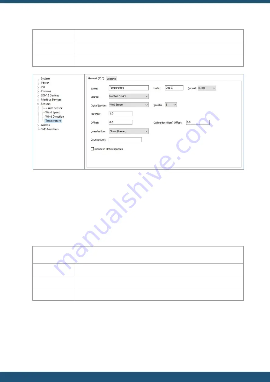
Modbus Device:
<Name given in step 3>
Variable:
3
Units:
Degrees C
14. Configure logging as required.
15. Click the
SEND CONFG
button to commit the settings to the iRIS.
3.8.3
Example of iRIS acting as a Slave Sensor
This section describes how to use iLink to configure the iRIS to provide information it has obtained from it analogue and
digital inputs to a Modbus Master, for example a Programmable logic controller (PLC).
The example also assumes that the PLC has been wired to the Serial Sensor Interface which has been configured correctly.
1. Connect to the iRIS with iLink and navigate to the configuration section.
2. Expand the Modbus Devices branch and select the first Device of the tree.
3. Give the device a name, this is used in the Virtual sensor configuration later.
4. Change the following:
Serial
Channel
Source:
SSI
Authority Roll:
Slave
Slave Address:
0
Endianness:
Little
Summary of Contents for iRIS Under Cover
Page 1: ...iRIS Under Cover User Manual ...
Page 13: ... 2022 HyQuest Solutions 13 Installation Figure 2 Mounting Diagram ...
Page 108: ... 2022 HyQuest Solutions 108 Appendices 8 1 Declaration of Conformity ...
Page 115: ... 2022 HyQuest Solutions 115 Appendices ...
Page 117: ...www hyquestsolutions com 2022 HyQuest Solutions 29 06 2022 ...


