7251 / 7351 Slide Gate Operator
INSTALLATION AND PROGRAMMING MANUAL
14
www.hysecurity.com • 800-321-9947
MX4514 Rev. A ©2019
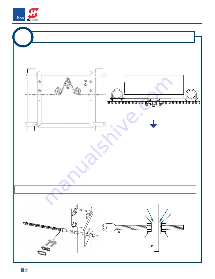
1. Route chain through sprockets as shown in IMAGE 3A-1. Make sure chain is level when attached to the
chain brackets. Chain should be aligned with all sprockets.
2. Attach the master link to one end of the chain and a chain bolt, then attach the chain bolt to a chain
bracket (IMAGE 3A-2).
3. Determine the required length of chain needed to attach the other chain bolt and still allow adjustment.
4. Using the proper chain breaking tool, cut and remove the excess chain.
5. Attach chain to chain bolt and connect to the second chain bracket.
NOTE:
Allow 1 inch of sag per 10 feet of chain.
3A
7251: ROUTE CHAIN AND CONNECT CHAIN BOLT
TOP VIEW
VIEW FROM
GATE SIDE
IMAGE 3A-1:
ROUTING CHAIN THROUGH OPERATOR GEARING
IMAGE 3A-2:
INSTALLING CHAIN BOLT TO CHAIN BRACKETS
WASHER
WASHER
LOCK WASHER
LOCK WASHER
CHAIN BOLT
NUT
NUT
CHAIN BRACKET
MASTER
LINK
TOWARD
GATE


