7251 / 7351 Slide Gate Operator
INSTALLATION AND PROGRAMMING MANUAL
29
MX4514 Rev. A ©2019
www.hysecurity.com • 800-321-9947
NOTE:
This input should only used with a 10-35 VDC power supply.
However, a battery is recommended as a backup.
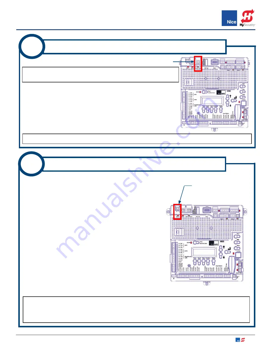
1. To wire Main DC Power panel connector, remove it from board for
wiring (IMAGE 13-1).
2. Strip wires from power supply back 3/8”-7/16” (10-11mm), twist, and
install into the connector screw terminals (positive to +, negative to
-), then plug back into board. (IMAGE 13-1).
12
MAIN DC POWER - INPUT CONNECTIONS
MAIN DC POWER INPUT CONNECTOR
NOTE:
LED below the terminal will glow red if mis-wired, and glow green if wired correctly.
IMAGE 13-1: MAIN
DC POWER INPUT CONNECTOR
SOLAR PANEL
INPUT CONNECTOR
IMAGE 14-1:
SOLAR CONNECTORS
A 20 Watt, or smaller, solar panel may be installed to enable battery
charging through the 1050 control board’s integral regulator/
conditioner as follows:
1. Assemble solar panel mounting bracket and panel with
included hardware.
2. Locate solar panel out of shadows of surrounding buildings,
walls, etc. and orient to collect the maximum sunlight energy
throughout the year.
In the northern hemisphere, mount panels
at upward angle of about 45 degrees with panel oriented
south. In the southern hemisphere orient the panel to face
north.
3. Cut off two battery lugs from the end of the solar panel cable.
4. Strip wires back 1/4”-5/16” (7-8mm), twist, and install into the
solar panel connector screw terminals on the control board
(RED = +, BLACK = -). See IMAGE 14A-1.
13A
SOLAR PANEL CONNECTION - 10W TO 20W
NOTES:
Turn ON Standby Mode if using only solar power to charge battery. If solar panel is wired
backwards, a red LED will illuminate above the connector.
For 30W solar panels and above, an external
regulator must be used. Nice offers a regulator (P/N SG-4) for this purpose. See INSTRUCTION 14B for
installation instructions for the SG-4 regulator.


