7251 / 7351 Slide Gate Operator
INSTALLATION AND PROGRAMMING MANUAL
33
MX4514 Rev. A ©2019
www.hysecurity.com • 800-321-9947
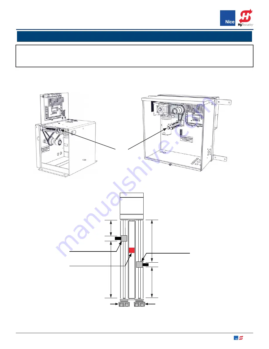
IMAGE 17-1:
7351 LIMIT ASSEMBLY
LOCATION
IMAGE 17-3:
7351 LIMIT ASSEMBLY FUNCTIONS
LIMIT
SENSOR
LIMIT
SENSOR
MAGNET
TOP VIEW
IMAGE 17-2:
7251 LIMIT ASSEMBLY
LOCATION
NOTE:
Until the control board has “LEARNED” the open/close limits, the OPEN and CLOSE buttons must be
pressed and HELD DOWN to operate the gate(s). Once limits are learned by the control board, it will take only
a single press (and release) to fully open or close the gate.
SECTION 12:
ADJUSTING GATE OPEN/CLOSE LIMITS
The limit assembly is located inside the control box between the circuit board and motor assembly (IMAGES
17-1 & 17-2). The limit assembly works by moving magnet along a rail as the gate opens or closes (IMAGE 17-3).
The position of a magnet sensor determines when the OPEN or CLOSE LEDs will light up and stop the gate
motor at either the chosen close or open limit.
INCREASE
TRAVEL FOR
MOVEMENT
TO THE
LEFT.
DECREASE
TRAVEL FOR
MOVEMENT
TO THE LEFT.
INCREASE
TRAVEL FOR
MOVEMENT TO
THE RIGHT.
DECREASE
TRAVEL FOR
MOVEMENT TO
THE RIGHT.
LIMIT ADJUSTMENT
KNOB FOR LEFT
MOVEMENT
LIMIT ADJUSTMENT
KNOB FOR RIGHT
MOVEMENT
LIMIT
ADJUSTMENT
ASSEMBLY


