8
© 2012 Installation and Reference Manual D0125 Rev. H
Section 2
— Getting Started
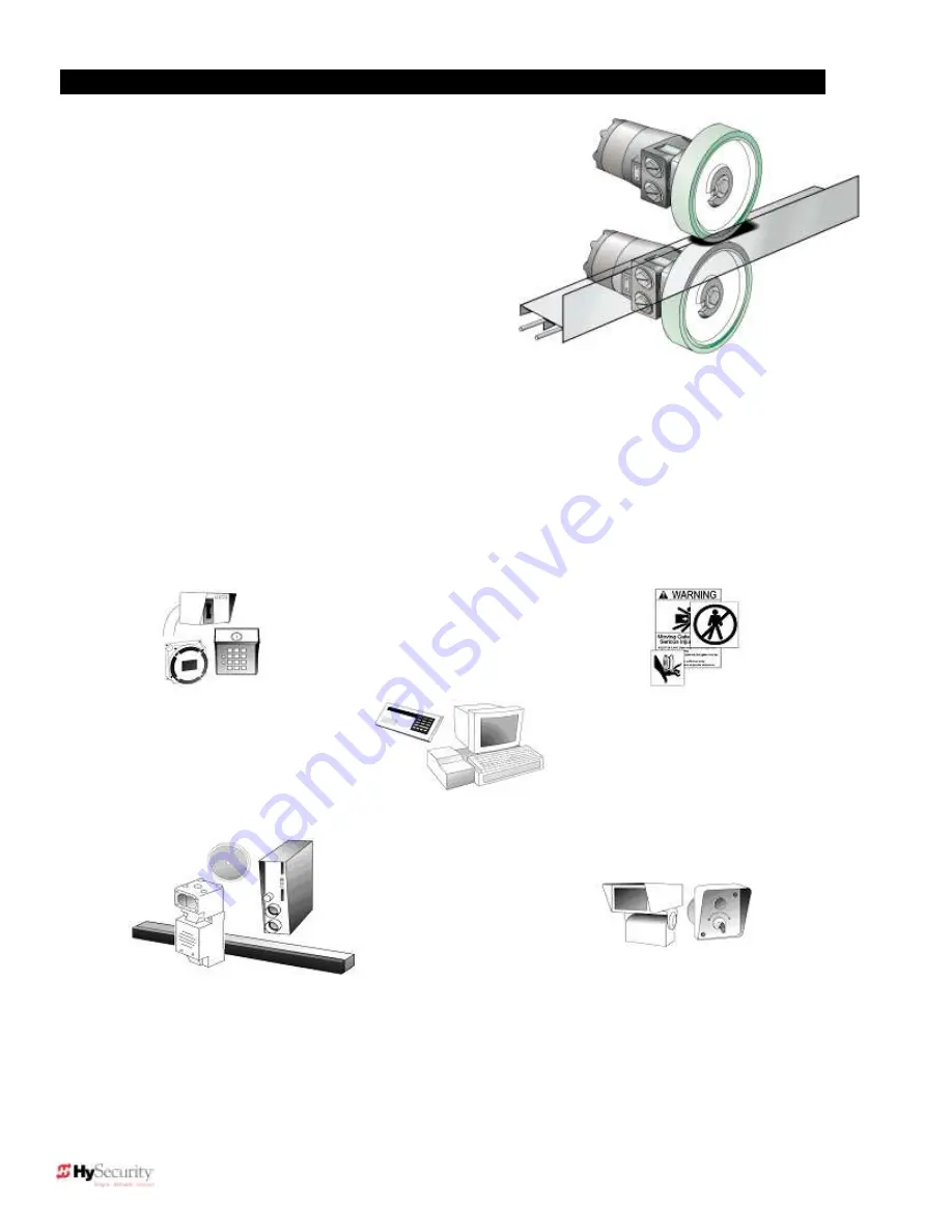
How this hydraulic operator works
HySecurity industrial slide gate operators rotate
polyurethane treaded drive wheels which grip a rigid metal
drive rail and feed it right or left during the gate travel. The
drive wheels are clamped above and below the drive rail
and are directly coupled to powerful hydraulic motors,
which easily move large gates. This simple yet durable
drive system is one of the unique features giving our
hydraulic operators their reputation for reliability.
Pedestrian Entrapment Protection
Before installing the gate operator, read and understand all the important information in Section 1. Be
absolutely certain that the required type and quantity of entrapment protection devices have been supplied
and that you understand how to install them correctly. Contact your local distributor with questions about
entrapment protection.
Accessory Compatibility
HySecurity hydraulic slide gate operators are fully compatible with all standard access control devices and
entrapment protection devices, some of which are listed below.
Security
Key Locks
Closed Circuit Television
Gate Position Indicator
Interlock/Sally Port
Gate Status Indicator
Entrapment
Protection/Obstruction
Sensing Devices
Inherent Sensing Device
Gate Edges
Photo Eyes
Vehicle Detectors (HY-5A)
Advanced Access Control
Access Control Interface
Card Reader
Keypad
Telephone Entry
Input/Output
Computer Interface
RS232/485
Information
Signs
Labels
Warnings
Basic Access Control
Radio Transmitter
Long Distance Control
Pushbutton Control Station
Programmable Time Clock
Card Reader
Summary of Contents for SlideDriver 50VF2
Page 2: ......
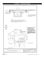
Page 28: ...14 2012 Installation and Reference Manual D0125 Rev H Section 2 Technical Drawings...
Page 29: ...15 2012 Installation and Reference Manual D0125 Rev H Section 2 Technical Drawings...
Page 36: ...22 2012 Installation and Reference Manual D0125 Rev H Section 3 Wiring Control Inputs...
Page 63: ...49 2012 Installation and Reference Manual D0125 Rev H Section 6 Internal Solenoid Lock Drawing...
Page 64: ...50 2012 Installation and Reference Manual D0125 Rev H Section 6 Internal Solenoid Lock Drawing...
Page 81: ...68 2012 Installation and Reference Manual D0125 Rev H...


