10
© 2012 Installation and Reference Manual D0125 Rev. H
Section 2
— Installation
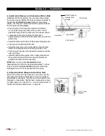
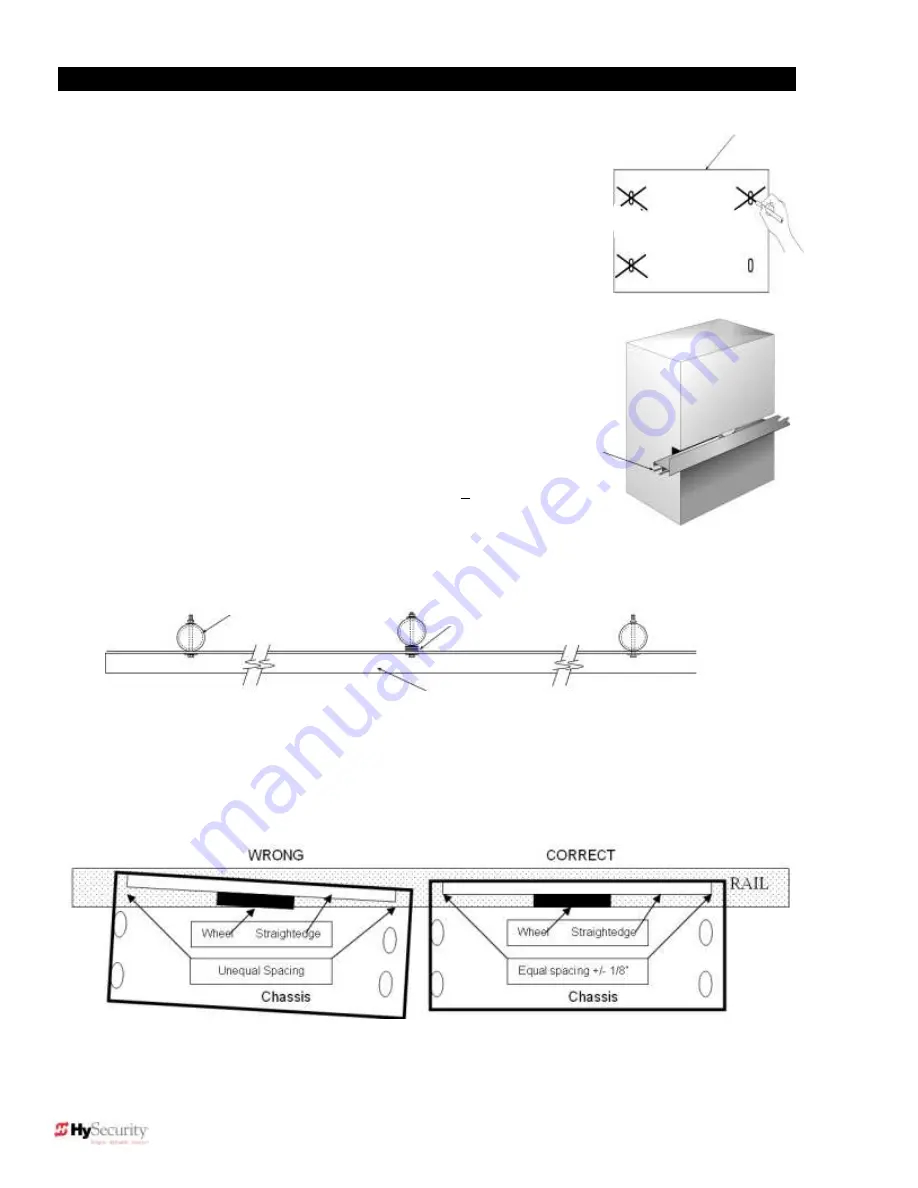
1. Drill four holes for concrete anchors
When you have removed the operator from its shipping container, cut out the
template found on the box. Use it to trace the outside edges and anchor slots.
Place the template on the concrete pad; making sure that it is parallel to and
1¾-inches from the gate. Trace the slots, remove the template, and then scribe
the locations for anchor bolts. Drill holes for the anchor bolts in the center of the
slots you marked so that you will have some room for adjustments. Install at
least four ½-inch x 4-inch concrete anchor bolts (two bolts per side).
2. Line up the operator
Put the operator in position onto the anchor bolts. Verify that the
operator is parallel (within ⅛-inch) and measure the distance between
the operator and the gate. It should be 1¾-inch away from the gate on
both the left and right sides. Refer to Figure A on page 9. Tighten the
anchors securely.
3. Bolt the Drive Rail to the Gate Panel
Connect multiple sections of drive rail together with ¼-inch roll pins for
a perfect splice. The drive rail must be bolted to each vertical member
of the gate panel. This may be done with U-bolt clamps or through
bolts. However, U-bolt clamps allow for easy up/down adjustment. If
the gate is bent or warped, shim the drive rail so that it is st ¼-
inch throughout the travel of the gate. When the drive rail has been
installed at the correct height, the top surface is 9¼-inches above the
operator base. A label and notch on each side of the operator indicates
the correct height. See Figure B on page 9.
Once the gate rail is straight, verify the alignment of the wheels to the rail. Place a straightedge (
≥
24-inch)
across the face of the upper wheel, through the rail slot in the face of the operator. The straightedge should be
in line with the rail and touching the aluminum rim of the wheel on across the face. The straightedge and rail
should be parallel within ⅛-inch over 24-inch. If not, loosen the chassis mounting bolts and rotate the chassis
until the straightedge and rail are parallel then retighten the chassis bolts.
slab
Roll pins
line up
drive rail
segments
to assure
perfect
splicing
Fencepost
Shim as
necessary
Drive rail
Summary of Contents for SlideDriver 50VF2
Page 2: ......
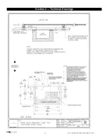
Page 28: ...14 2012 Installation and Reference Manual D0125 Rev H Section 2 Technical Drawings...
Page 29: ...15 2012 Installation and Reference Manual D0125 Rev H Section 2 Technical Drawings...
Page 36: ...22 2012 Installation and Reference Manual D0125 Rev H Section 3 Wiring Control Inputs...
Page 63: ...49 2012 Installation and Reference Manual D0125 Rev H Section 6 Internal Solenoid Lock Drawing...
Page 64: ...50 2012 Installation and Reference Manual D0125 Rev H Section 6 Internal Solenoid Lock Drawing...
Page 81: ...68 2012 Installation and Reference Manual D0125 Rev H...


