11
© 2012 Installation and Reference Manual D0125 Rev. H
Section 2
— Installation
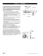
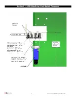
4. Install Limit Ramps on Underside of Drive Rail
SlideDriver 50VF2/3 operators have two sets of limit ramps.
The ramps mounted farthest from the operator and closest to
the gate are
deceleration ramps
(these are the longest
ramps). The ramps mounted closest to the operator, farthest
from the gate are
stop ramps
.
Push the gate to the fully closed position and drill two
⅜-inch holes through the drive rail to mount a 12-inch
plastic limit ramp under the drive rail, in the wheel channel.
Locate drive rail so that it will trip the limit switch
approximately. 2-inches before the exact spot you want the
gate to stop.
Adjust the ramp left or right to achieve exact stopping point.
Fully secure by tightening both bolts.
Adjust the lever arms on the limit switch so that the roller
clears the underside of the drive rail by at least ¼-inch.
Push the gate fully open and repeat this procedure with the
other limit ramp.
Install the deceleration ramps in the outside (farthest from
the operator) channel of the drive rail, with the flat end
parallel to the flat end of the stop ramp.
NOTE:
Be sure to use both
deceleration
ramps,
(approximately 29 inches long and approximately 11 inches
long) to make the total
deceleration
ramp 40 inches long.
See pages 16 and 17 for expanded limit ramp views.
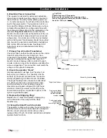
5. Clamp the Drive Wheels to the Drive Rail
When the wheels are fully clamped on the drive rail, the
red spring should be compressed to 2-inch in height. If
adjustment is necessary, turn the nut at the bottom of the
threaded rod assembly. Slightly less compression is okay
for lighter gates. See
Section 8
— Use and Adjustment of
the Manual Release Mechanism
on page 58.
Limit ramp
Drive rail
Limit Roller
Limit switch
Drill 2 holes to
secure limit
ramps.
Summary of Contents for SlideDriver 50VF2
Page 2: ......
Page 28: ...14 2012 Installation and Reference Manual D0125 Rev H Section 2 Technical Drawings...
Page 29: ...15 2012 Installation and Reference Manual D0125 Rev H Section 2 Technical Drawings...
Page 36: ...22 2012 Installation and Reference Manual D0125 Rev H Section 3 Wiring Control Inputs...
Page 63: ...49 2012 Installation and Reference Manual D0125 Rev H Section 6 Internal Solenoid Lock Drawing...
Page 64: ...50 2012 Installation and Reference Manual D0125 Rev H Section 6 Internal Solenoid Lock Drawing...
Page 81: ...68 2012 Installation and Reference Manual D0125 Rev H...


