17
© 2012 Installation and Reference Manual D0125 Rev. H
Section 2
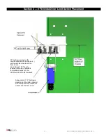
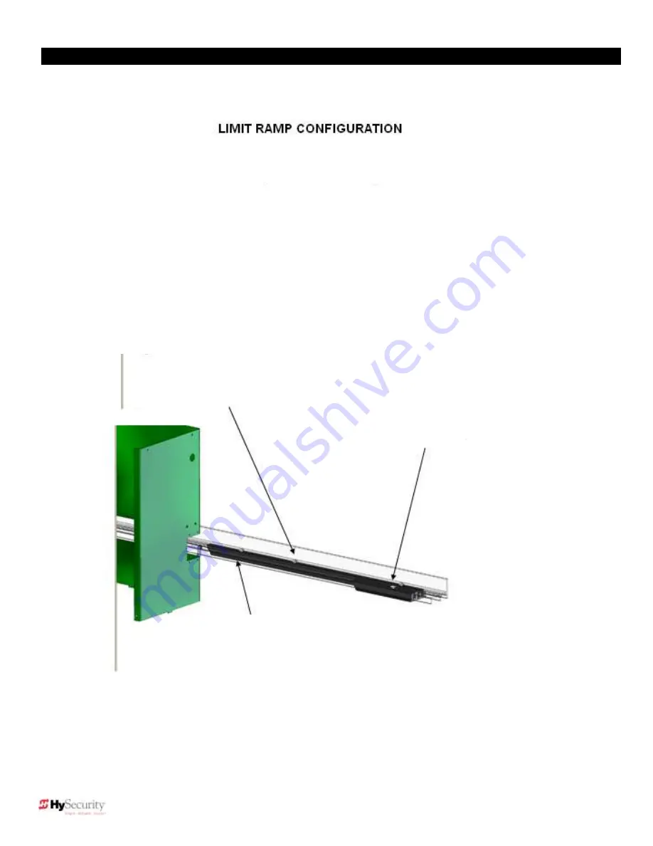
— Limit Ramp Configuration
NOTE:
For the EFO, refer to
the setup and programming
instructions on page 20.
11.5″ limit ramp placed along the inside
channel with the tapered end toward the
wheels and the flat end out.
30″ limit ramp placed in the outside
channel with the tapered end toward the
wheels and the flat end out.
An additional 10.5″ double-tapered limit
ramp is placed in the outside channel
on the all models.
SlideDriver 50VF2/3
Summary of Contents for SlideDriver 50VF2
Page 2: ......
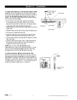
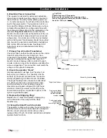
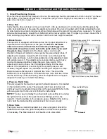
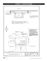
Page 28: ...14 2012 Installation and Reference Manual D0125 Rev H Section 2 Technical Drawings...
Page 29: ...15 2012 Installation and Reference Manual D0125 Rev H Section 2 Technical Drawings...
Page 36: ...22 2012 Installation and Reference Manual D0125 Rev H Section 3 Wiring Control Inputs...
Page 63: ...49 2012 Installation and Reference Manual D0125 Rev H Section 6 Internal Solenoid Lock Drawing...
Page 64: ...50 2012 Installation and Reference Manual D0125 Rev H Section 6 Internal Solenoid Lock Drawing...
Page 81: ...68 2012 Installation and Reference Manual D0125 Rev H...


