20
© 2012 Installation and Reference Manual D0125 Rev. H
Section 3
— 50VF2/3 EFO: Setting the Emergency Fast Operate
NOTE:
For a wiring schematic of the 50VF2-EFO, refer to the Appendix, page
66.
To enable the Emergency Fast Operate option on the SlideDriver 50VF2-EFO,
you need to program the Smart Touch Controller by taking the following steps:
NOTE:
Since you are in programming mode the buttons on the keypad change
from OPEN, CLOSE, and STOP to PREVIOUS, NEXT, and SELECT. See the
illustrations.
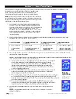
1. Make sure the operator is turned ON. RD 00 appears on the VFD display
and a gate status (
,
, or
) appears on the Smart Touch
Controller which indicates the machine is operational.
2. Press the PROGRAM button twice. The close timer menu item appears on
the display which indicates you have accessed the User Menu.
3. While the close timer remains displayed, press and hold the RESET button and then
the OPEN button. Hold the buttons for two seconds and then release both buttons.
#
appears on the display which indicates you have accessed the Installer Menu.
(The number appearing after
indicates the operator’s usage class.)
4. Press NEXT until the Emergency Close,
appears on the display.
5. Press SELECT and
starts blinking which indicates the display can be
changed.
6. Press NEXT or PREVIOUS to change the display to
(which enables
“emergency close).
7. Press SELECT to accept the entry. (The characters on the display stops
blinking.)
8. Press PROGRAM to exit programming mode and return to Run Mode.
Install a Push-Button Device
The Emergency Fast Operate (3ft/s emergency close option) is designed for a
constant hold function, such as a push-button device that is held for the duration of gate travel. To operate properly, the
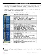
device must be connected to Terminal 23 on the Smart Touch Controller and a +24VDC terminal in the control box. See
the illustration on the next page.
When the connections are made, a constant hold signal transmitted to the Smart Touch Controller causes the Emergency
Fast Operate function to close the gate at 3ft/s.
Test the Operator
Complete the installation by testing the operation of the gate.
1. Make sure the operator is turned ON.
2. Close the control box lid.
3. Press OPEN to open the gate. The gate should open at 2ft/s.
4. Access gate operation. Observe the travel speed of the gate when you press the EMERGENCY CLOSE (on the
constant hold device).
5. If the gate closes at 3ft/s, the operator is working properly. If additional accessories are to be added, read about
Wiring Control Inputs
on the next page.
NOTE
: The # symbol shown in the
example display will appear on your
operator as a number (0 to 99).
Summary of Contents for SlideDriver 50VF2
Page 2: ......
Page 28: ...14 2012 Installation and Reference Manual D0125 Rev H Section 2 Technical Drawings...
Page 29: ...15 2012 Installation and Reference Manual D0125 Rev H Section 2 Technical Drawings...
Page 36: ...22 2012 Installation and Reference Manual D0125 Rev H Section 3 Wiring Control Inputs...
Page 63: ...49 2012 Installation and Reference Manual D0125 Rev H Section 6 Internal Solenoid Lock Drawing...
Page 64: ...50 2012 Installation and Reference Manual D0125 Rev H Section 6 Internal Solenoid Lock Drawing...
Page 81: ...68 2012 Installation and Reference Manual D0125 Rev H...


