20
© 2012 Installation and Reference Manual D0125 Rev. H
Section 3
— Wiring Control Inputs
1. Test the open and close function of the gate before wiring to accessory devices (external control inputs). This makes it
easier to troubleshoot if an unexpected functionality arises. The Smart Touch Controller has a tact button you can
push which lights an LED next to the active inputs. This button is in bottom left corner of the Smart Touch Controller
board.
2. All the Smart Touch Controller inputs listed below are shown as a single input. The second wire is connected to the
Common Terminal Bus (COM) on the Smart Touch Controller.
NOTE
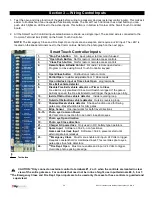
: The Emergency Close and Fire Dept. Open inputs are an exception and require a +24V input. The +24V is
located on the spade terminals next to the Common Bus. Refer to the photograph on the next page.
Smart Touch Controller Inputs
1.
*Stop Push button
N.C. input, jumper to Common if unused
2.
*Open Push Button
Not for radio or remote access controls
3.
*Close Push button
Not for radio or remote access controls
4.
Remote Open & Radio Control
For radio / remote open device –
Program to Close using Smart Touch Controller keypad
5.
Open/Close button
Pushbutton or radio controls
6.
Partial Open
Installer adjustable from 7- 99 seconds
7.
Open interlock input or Time clock Open
programmable
8.
Free Exit vehicle detector
9.
Disable Free Exit vehicle detector or Timer to Close
Free Exit is only disabled if Close Limit Switch is tripped. If the gate is
partially opened, the Free Exit detector will trigger the gate to open fully.
10.
Inside Obstruction vehicle detector
Inside reversing loop
11.
Outside Obstruction vehicle detector
Outside reversing loop
12.
Shadow/Reset vehicle detector
Shadow function used for Swing
gates only - Reset function is for Arm gates
13.
Edge Sensor
One input works for both travel directions
14-15.
Photo eye Common Power
24V common connection for open and close photo eyes
17.
Photo eye Open direction
19.
Photo eye Close direction
21.
Charger AC power loss
Only used in DC, battery type operators
22.
Spare Input
Software ≤ h3.26,- non functional,
Gate Lock Interlock Input
Software > h3.26, prevents start until
external gate lock releases
23.
**Emergency Close
Must menu enable and input +24 Volts to trigger.
Requires constant hold or maintained input. This overrides photo eyes,
gate edges & vehicle detectors.
24.
**Fire Dept. Open
Must menu enable and input +24 Volts to trigger.
Overrides photo eyes & gate edge.
CAUTION: *Only connect an external control to terminals #1, 2 or 3 when the controls are located in clear
view of the entire gate area. For controls that need not be in line of sight, use input terminals #4, 5, 6 or 7.
**The Emergency Close and Fire Dept. Open inputs are to be used only if access to these controls is guarded and
supervised.
Tact button
Summary of Contents for SlideDriver 50VF2
Page 2: ......
Page 28: ...14 2012 Installation and Reference Manual D0125 Rev H Section 2 Technical Drawings...
Page 29: ...15 2012 Installation and Reference Manual D0125 Rev H Section 2 Technical Drawings...
Page 36: ...22 2012 Installation and Reference Manual D0125 Rev H Section 3 Wiring Control Inputs...
Page 63: ...49 2012 Installation and Reference Manual D0125 Rev H Section 6 Internal Solenoid Lock Drawing...
Page 64: ...50 2012 Installation and Reference Manual D0125 Rev H Section 6 Internal Solenoid Lock Drawing...
Page 81: ...68 2012 Installation and Reference Manual D0125 Rev H...


