27
© 2012 Installation and Reference Manual D0125 Rev. H
Section 3
—Installer Menu Functions
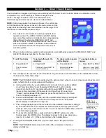
The Installer Menu functions shown in the chart on previous page are described in more detail on the next few pages.
Installer 1
[
]
Set UL Usage Class:
Assign the operator’s Usage Class designation per UL 325 standards. The
installer must designate a usage class before the operator will function. See page 19.
Installer 2
[
]
Set Handing of gate
The handing determines which way the gate opens as you view it from the
operator side. The installer must designate a left or right handing before the operator will function. See page 19.
Installer 3
[
]
Load Factory Defaults:
Globally restores all menu settings back to new machine status. To
activate, change the setting from 0 to 1 and press the PROGRAM button. Note that if the factory defaults are reinstated,
the UL usage class, handing, and buzzer type will need to be set again.
Installer 4
[
]
Select Buzzer Type:
Selects the type of audible buzzer installed on the machine. To set, press the
SELECT button; the display flashes 0. Press OPEN and listen to the buzzer volume, and then press OPEN again and
listen to the buzzer volume. If the volume increased, press SELECT to change to the louder volume. If the volume
decreased, push CLOSE to retain the louder volume then push SELECT to lock in the louder volume.
Installer 5
[
]
Set Solo, Master/Slave type, or Sally Port:
Programs and establishes communication protocols
when wiring two operators as dual gates in a Master/Slave or Sally Port site configuration. This menu item appears when
the sequenced gate menu item (
) is set to 0 (off). Settings: 1 = Slave, 2 = Master, 3 = Sally Port A, 4 = Sally Port B
Installer 6
[
]
Set Sequential Gate status:
Programs and establishes communication protocols when wiring two
operators as sequential gates. This menu item appears when the sequenced gate menu item (
) is set to 0 (off).
Settings: 1 = Loop layout #1, 2 = Loop Layout #2
Installer 7
[
]
Set AC Charger or Solar:
Appears on 24VDC battery (UPS) machines only.
Installer 8
[
]
Enable Fire Dept. Open:
Enables the Fire Department Open input. When set to [
], overrides
vehicle detectors, photo eyes and gate edges to open a gate. A reset (or two open commands) is required before the
gate can be closed.
Installer 9
[
]
Enable Emergency Close:
Enables the Emergency Close input. When set to [
], overrides
vehicle detectors, photo eyes and gate edges to close a gate. A reset is required before the gate can be opened. (EFO
model only)
Installer 10
[
]
Inherent Sensor sensitivity:
Adjusts the sensitivity of the internal inherent sensor. Available
settings are 1-9 with 9 being the least sensitive.
Installer 11
[
]
Inherent Sensor function:
Only available in UL Class 4 Gate Operators and allows an option
whereby the inherent sensor will only stop the gate.
Installer 12
[
]
Leaf delay Close:
Only appears if the Gate Operator is set up as a Master or a Slave. Available
settings are 1-7. Each increment adds ½ second, to a maximum of 3 ½ seconds time delay, before the operator activates
when commanded to close.
Installer 13
[
]
Leaf delay Open:
Only appears if the Gate Operator is set up as a Master or a Slave. Available
settings are 1-7. Each increment adds ½ second (with a maximum of 3 ½ seconds) time delay following a command to
open before the operator activates.
Installer 14
[
]
Maximum run timer:
Allows an optional setting of 300 seconds if changed to [
] as opposed to
the maximum run timer default setting of 60 seconds.
Installer 15
[
]
Partial Open distance:
Activates the partial open input and allows an adjustable distance by setting
the open duration. The available time settings are 7-99 seconds. The default setting [
] leaves this input inactive.
Installer 16
[
]
PEC (photo eye close) reverse to open:
The default setting is non-reversal if the close photo eye is
triggered. The optional setting of [
] will cause the gate to reverse to open for two seconds if triggered while closing.
Summary of Contents for SlideDriver 50VF2
Page 2: ......
Page 28: ...14 2012 Installation and Reference Manual D0125 Rev H Section 2 Technical Drawings...
Page 29: ...15 2012 Installation and Reference Manual D0125 Rev H Section 2 Technical Drawings...
Page 36: ...22 2012 Installation and Reference Manual D0125 Rev H Section 3 Wiring Control Inputs...
Page 63: ...49 2012 Installation and Reference Manual D0125 Rev H Section 6 Internal Solenoid Lock Drawing...
Page 64: ...50 2012 Installation and Reference Manual D0125 Rev H Section 6 Internal Solenoid Lock Drawing...
Page 81: ...68 2012 Installation and Reference Manual D0125 Rev H...

