800-321-9947
www.hysecurity.com
D0482 Rev B Page 1
Manual addendum
SlideDriver 50VF series
June 1, 2012
D0125 Rev H D0119 Rev J
Notifications
Screen Mesh on Gate Height:
Per UL 325 and ASTM 2200 Standards, all openings in a sliding gate up to a
72-inch (6 foot or 183 cm) height must be guarded or screened. Note that all references to the 48-inch (4ft
or 122 cm) screen mesh height in the manual are incorrect.
HySecurity Upgrades
ModBus:
New communications protocol
constantly monitor the Variable Frequency Drive (VFD) and record events in the STC
history log. The history log is easily accessible using the HySecurity S.T.A.R.T.
program and a PC laptop computer.
The new communication protocol reduces intermittent operator issues caused by site
power quality issues and the STC resets VFD faults or error codes upon receiving a new
command which eliminates unnecessary field calls. It also provides smoother
acceleration and deceleration.
All 50VF2/3 SlideDrivers shipped after January 1, 2012 will have the new ModBus
cable and communication protocol installed. If you need replacement parts for your existing 50VF series
operators, be sure to have the serial number of the operator available when you order parts.
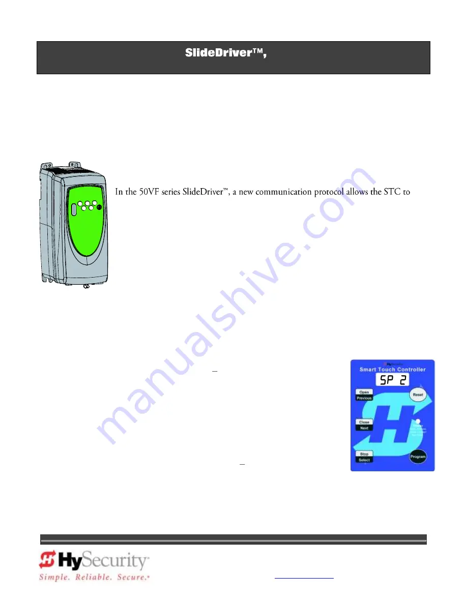
New SlideDriver configuration as of June 1, 2012: If you install a new 50VF2/3 operator, the speed
is factory set at 2 foot per second (2 ft/s). To change the speed, you will need to
access the Installer Menu. Refer to
Section 3 Smart Touch Basics
in the manual.
sets the 50VF2/3 speed to approximately 2 ft/s.
sets the 50VF2/3 speed to approximately 3 ft/s.
and
are not used. (The operator will not run if you change the
speed setting to 0 or 1.)
NOTE: To enable Emergency Fast Operate (EFO), you also need to set the
Emergency Close Mode (
= 1). Refer to
Section 3 Setting the Emergency Fast
Operate
. If you set the speed and receive an ERR6, check the cable & wiring
connections between the VFD and STC.
Summary of Contents for SlideDriver 50VF2
Page 2: ......
Page 28: ...14 2012 Installation and Reference Manual D0125 Rev H Section 2 Technical Drawings...
Page 29: ...15 2012 Installation and Reference Manual D0125 Rev H Section 2 Technical Drawings...
Page 36: ...22 2012 Installation and Reference Manual D0125 Rev H Section 3 Wiring Control Inputs...
Page 63: ...49 2012 Installation and Reference Manual D0125 Rev H Section 6 Internal Solenoid Lock Drawing...
Page 64: ...50 2012 Installation and Reference Manual D0125 Rev H Section 6 Internal Solenoid Lock Drawing...
Page 81: ...68 2012 Installation and Reference Manual D0125 Rev H...


