38
© 2012 Installation and Reference Manual D0125 Rev. H
Section 5
—Detector Loop Installation
Detector Basics
The vehicle detector passes a small current flow through the “loop” which then becomes an inductive coil.
When a vehicle passes over a loop the detector senses the resultant drop in the inductance, and actuates the detector
output.
Loop Configurations
Configurations differ depending on the application. In parking applications with our StrongArm operator (HTG 320), a loop
may be as small as 4ft x 6ft (1.2m x 1.8m). In traffic applications employing one of our sliding gate operators, or swing
gate operators, the smallest loop should not be less than six feet square.
Rules to Follow for Security Gate Applications
NOTE
: Refer to the drawing on page 40.
1. The side of the loop closest to the gate shall be located at least 4 feet (1.2 meters) distant from its line of travel.
2. The shortest side of the loop shall be between 6 and 8 feet (1.8 and 2.4 meters) in length. The longest side of the loop
shall be between 6 and twenty 20ft (1.8 and 6m) in length. For applications that need to span a wide area, use several
smaller loops. Do not exceed a maximum of 200ft
²
of loop area (61m
²
) to only one detector.
3. In applications with multiple loops, keep each loop at least 6ft (1.8m) apart. This avoids “cross talk”. It is possible to
have loops closer together by selecting different frequencies. An advantage of using HySecurity model HY-5A
detectors is that problematic “cross talk” is not possible.
4. For greater sensitivity and less chance of false calls caused by the motion of the gate, it is better to use multiple
smaller loops, connected in a series circuit, to one detector instead of one large, single loop.
5. To avoid interference, keep loops at least 2 inches (5cm) above any reinforcing steel. Do not route loop wires with, or
in close proximity to, any other conductors, including other loop leads, unless shielded lead-in cable is used. Never
route high voltage circuits in PVC conduit near a loop.
6. Loop and lead-in wire should be one continuous piece. Avoid splices, if possible. If a splice is necessary for any
reason, “pot” the splice in epoxy or use heat shrink to ensure that the quality of the splice covering is the same as the
original wire jacket.
7. Use only number 14, 16, or 18 gauge stranded wire with a direct burial jacket. Cross linked polyethylene insulation
types, such as, XLPE or XHHW, will last much longer and are less prone to damage during installation than
conventional insulation types. Preformed loops can be used before road surfacing or under pavers.
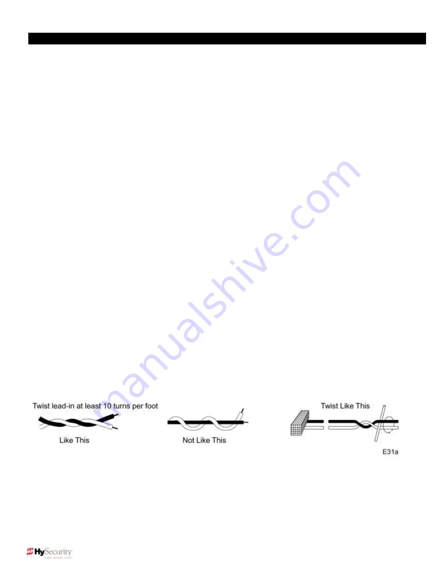
8. Twist loose tails of lead-in wires tightly, approximately 10 turns per foot (10 times per 30cm).
Summary of Contents for SlideDriver 50VF2
Page 2: ......
Page 28: ...14 2012 Installation and Reference Manual D0125 Rev H Section 2 Technical Drawings...
Page 29: ...15 2012 Installation and Reference Manual D0125 Rev H Section 2 Technical Drawings...
Page 36: ...22 2012 Installation and Reference Manual D0125 Rev H Section 3 Wiring Control Inputs...
Page 63: ...49 2012 Installation and Reference Manual D0125 Rev H Section 6 Internal Solenoid Lock Drawing...
Page 64: ...50 2012 Installation and Reference Manual D0125 Rev H Section 6 Internal Solenoid Lock Drawing...
Page 81: ...68 2012 Installation and Reference Manual D0125 Rev H...


