46
© 2012 Installation and Reference Manual D0125 Rev. H
Section 6
— 24-Hour, 7 Day Time Option
This is an option you can order from HySecurity. The timer generates an open command which will hold the gate open
until it is released. Instructions on how to use and program it accompany the timer.
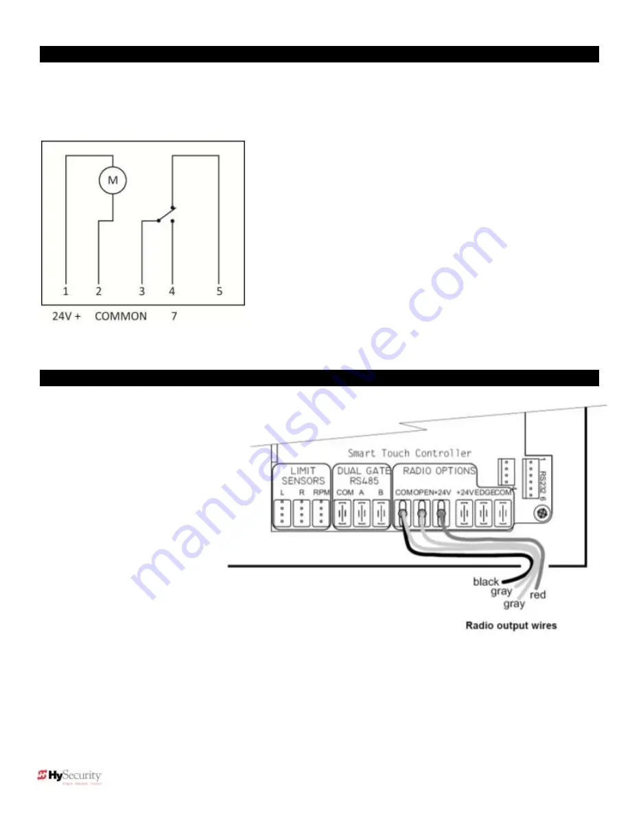
To connect the optional timer to the Smart Touch Controller, use the following schematic:
Connect the Timer Power Pin 1 to 24V (+)
Connect the Timer Power Pin 2 to COM
Connect the Timer Com Pin 3 to COM
Connect Timer NO Pin 4 to #7, Time Clock Open
Section 6
–Radio Remote Open Option
Mount a commercial style 24VDC
radio receiver (external antenna
type) on the inside of the operator,
below the electrical box. Knock out
the smallest hole in the lower right
corner of the electrical box and
route the wires to the area marked
Radio Options. Only three wire
connections are needed because
the 24-Volt supply and the radio
output share a wire. Being certain to
observe polarity, crimp the black
radio power wire together with one
of the radio output wires into a .25”
spade connector and connect to the
COM terminal. Connect the red wire
to the +24V terminal and connect
the other radio output contact wire
to the spade marked OPEN. Note that this terminal is the same as the #4 input terminal labeled REMOTE OPEN AND
RADIO CONTROL on the main control board.
Mount an external antenna onto the top of a fixed post of the fence near the operator.
Connect the antenna into the socket on the radio receiver.
Set the “DIP” switches in the receiver to match the same code used in the transmitter.
If there is also to be an edge sensor transmitter to reverse the gate, be certain to use a two channel commercial receiver.
Remember that each transmitter and receiver must have their codes set the same or they will not function.
Summary of Contents for SlideDriver 50VF2
Page 2: ......
Page 28: ...14 2012 Installation and Reference Manual D0125 Rev H Section 2 Technical Drawings...
Page 29: ...15 2012 Installation and Reference Manual D0125 Rev H Section 2 Technical Drawings...
Page 36: ...22 2012 Installation and Reference Manual D0125 Rev H Section 3 Wiring Control Inputs...
Page 63: ...49 2012 Installation and Reference Manual D0125 Rev H Section 6 Internal Solenoid Lock Drawing...
Page 64: ...50 2012 Installation and Reference Manual D0125 Rev H Section 6 Internal Solenoid Lock Drawing...
Page 81: ...68 2012 Installation and Reference Manual D0125 Rev H...


