52
© 2012 Installation and Reference Manual D0125 Rev. H
Section 7
— STC Troubleshooting
The Smart Touch Controller (STC) includes many self diagnostics. Specific messages appear on the display and the
Audio Alert buzzer sounds distinctive chirps. Any Alerts, Faults or Errors are also logged into memory and date/time
stamped. For diagnostic purposes these messages can be retrieved with optional START software available from
HySecurity (see bottom of page 31). The following chart lists problem codes detected by the Smart Touch Controller.
Updates to this chart appear on HySecurity’s website at www.hysecurity.com
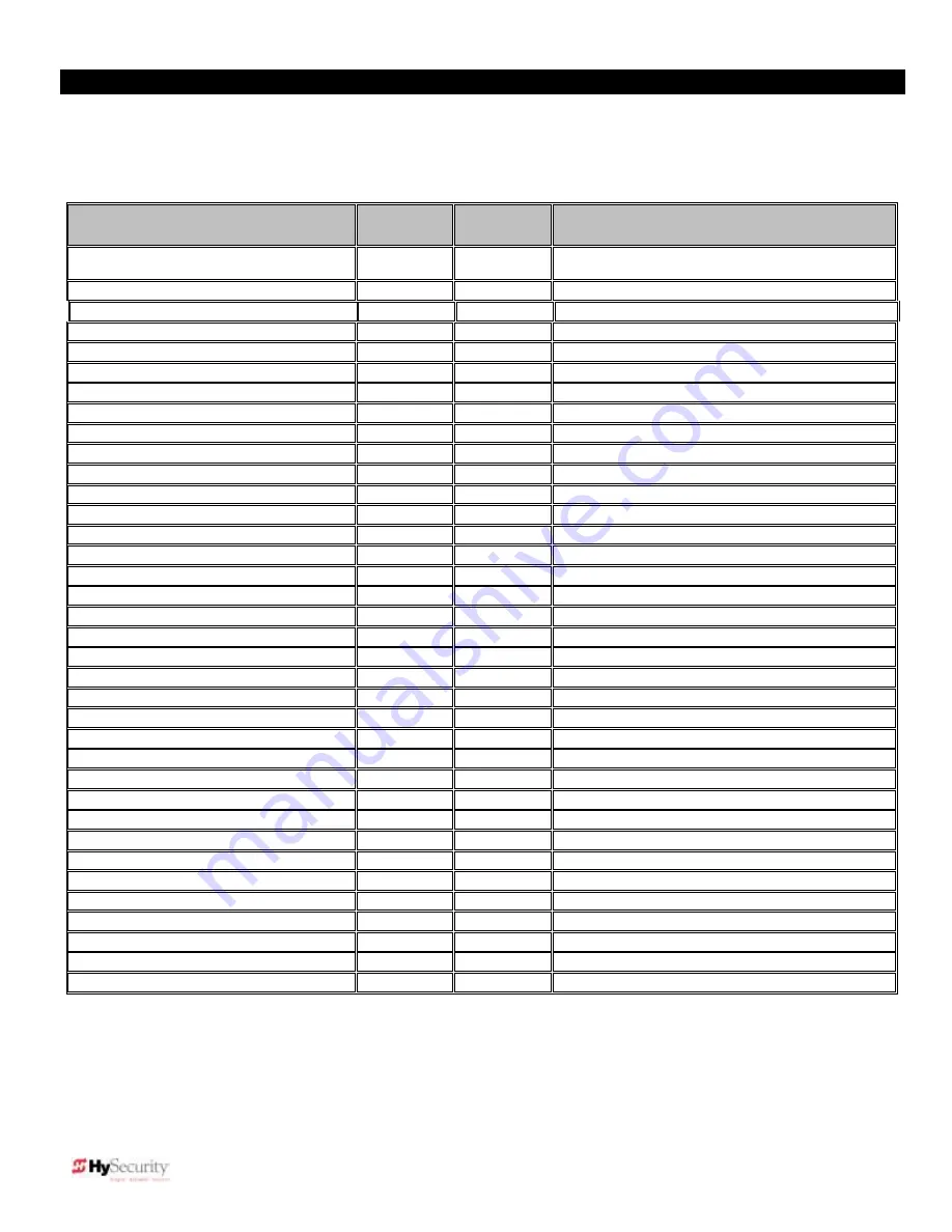
Error, Fault, or Alert Status
LCD
Display
Reads
Buzzer Chirp Sequence
Cannot respond due to tripped IES sensor or
operator is in entrapment mode
Entr
2 chirps/sec every 2 seconds while control input is
active
Safety Mode Alert
SAFE
2 chirps once when in Safety Mode
Low 24V Control Voltage Alert (AC or DC)
Lo24
N/A (display flashes 1 sec every 5 seconds)
Critical Low Power (AC or DC )
bAdP
1 chirp every 3s – controls disabled
Dead 24V Battery Alert – DC only
bat – dEAd
3 chirps upon any operating command
Gate Forced Open Alert
ALE1
2 pulses/sec for 30 seconds
Gate drift closed Alert
ALE2
2 pulses/sec for 10 seconds
Motor thermal overload Alert
ALE4
2 chirps/sec once every 15 seconds
Both Limits Tripped Alert
ALE5
2 chirps/sec every 15 seconds
Limits not released in 10 seconds
ALE6
2 chirps/sec every 15 seconds
Loop detector freq change alert
ALE7
2 chirps/sec every 15 seconds
Loop shorted to ground alert
ALE8
2 chirps/sec every 15 seconds
Loop open (disconnected) alert
ALE9
2 chirps/sec every 15 seconds
Loop detector comm. alert
AL10
2 chirps/sec every 15 seconds
Loop detector failed alert
AL11
2 chirps/sec every 15 seconds
Loop detector active >5 minutes
AL12
2 chirps/sec every 15 seconds
General I2C Comm. Buss failure
AL16
2 chirps/sec every 15 seconds
Bad 3V coin battery
AL17
2 chirps/sec every 15 seconds
False slow down signal
AL19
2 chirps/sec every 15 seconds
Lock Intrlk (Input #22) Blocks Open
AL20
2 chirps/sec every 15 seconds
VFD Error Alert
AL21
2 chirps/sec every 15 seconds
Dual/Seq. Gate communication lost
AL22
2 chirps/sec every 3 seconds
Maximum Run Fault
FAL1
1 chirp once every 15 seconds
Photo eye Fault (supervised)
FAL2
2 chirps/sec once per minute
Critical AC sag – bad supply wire
FAL3
2 chirps/sec once per minute
Open or Closed limit failed
FAL5
2 chirps/sec once per minute
Directional Motion Error
Err1
3 chirps/sec once per minute
Disconnected IES Error
Err2
3 chirps/sec once per minute
Serial comm. internal Error
Err3
3 chirps/sec once per minute or 3 on Cmd.
Serial comm. mast/slave Error
Err4
3 chirps/sec once per minute
STC-VFD Communications Error
Err6
3 chirps/sec once per minute
EEPROM Data Error (factory)
Err7
3 chirps/sec once per minute
EEPROM Data Error (installer)
Err8
3 chirps/sec once per minute
EEPROM Data Error (user menu)
Err9
3 chirps/sec once per minute
Open or Close slow down switch failed
Er10
3 chirps/sec once per minute
Memory Checksum Error
Fail
3 chirps/sec once per minute
NOTE:
The green LED near the “coin” battery on Smart Touch Controller is the “heartbeat” of the processor. This LED
always blinks at a steady pace which indicates normal operation.
Gate Speed:
The gate speed is determined by the size of the hydraulic operator’s pump and its actuator components. Just like a gear
box, this speed is not adjustableDo not attempt to slow a gate by changing a valve setting. If the speed of a gate must be changed,
contact your HySecurity distributor. Extremes in temperature usually does not affect the speed of the gate. HySecurity hydraulic gate
operators use a special fluid called
Uniflow
, which maintains a linear viscosity over a broad range of temperatures. HySecurity operators
are rated for service in ambient temperatures of -40°F to 158°F. If the speed of your operator is affected by temperature, verify that the
gate hardware is not impaired and check that the reservoir is filled with
Uniflow
. Consider adding a heater in extreme weather.
Summary of Contents for SlideDriver 50VF2
Page 2: ......
Page 28: ...14 2012 Installation and Reference Manual D0125 Rev H Section 2 Technical Drawings...
Page 29: ...15 2012 Installation and Reference Manual D0125 Rev H Section 2 Technical Drawings...
Page 36: ...22 2012 Installation and Reference Manual D0125 Rev H Section 3 Wiring Control Inputs...
Page 63: ...49 2012 Installation and Reference Manual D0125 Rev H Section 6 Internal Solenoid Lock Drawing...
Page 64: ...50 2012 Installation and Reference Manual D0125 Rev H Section 6 Internal Solenoid Lock Drawing...
Page 81: ...68 2012 Installation and Reference Manual D0125 Rev H...


