REFERENCE
Installing a Lock for 12VDC or 24VDC
Systems
To install a lock for 12VDC or 24VDC systems, take
the following steps:
1.
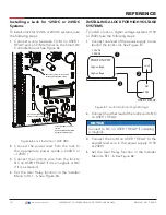
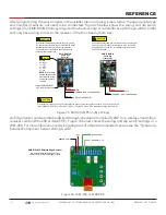
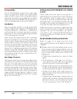
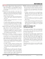
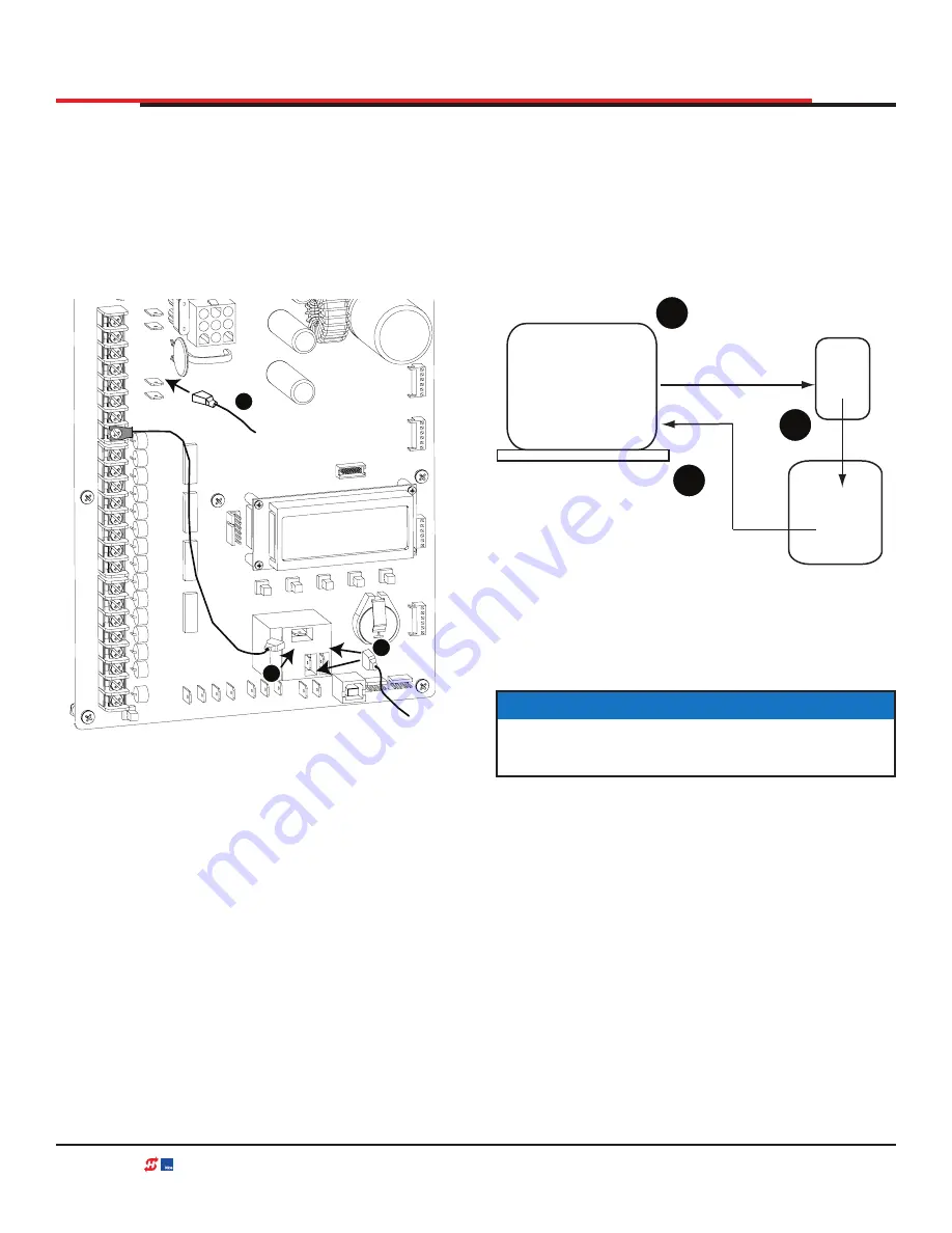
Connect a wire between COM on USER 1
RELAY and a COM terminal on the Smart DC
Controller board. See Figure 66
.
Figure 66. Lock Installtion 12/24 VDC
2.
Connect the power lead from the lock to
the appropriate power spade (+24VDC or
+12VDC)
3.
Connect the common wire from the lock to
NC on USER 1 RELAY if it is a maglock or NO
if it is a solenoid.
4.
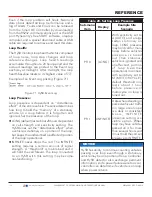
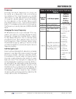
Set the User Relay function in the Installer
Menu to RL1 - 6. See Figure 68
.
COM
COM
COM
COM
COM
COM
COM
COM
STOP
OPEN
RADI
O
CLOSE
OPEN
SENSOR
2
SENSOR
3
SENSOR
3
EXIT
LOOP
OPEN
PARTIAL
BLOCK
EXIT
IN OBS
LOOP
OUT OBS
LOOP
CENTER
LOOP
SENSOR
COM
+ 24 V
EMERG
OPEN
SHOW
LEDs
U
SE
R2
COM NO
DC
USER 1 RELAY
NO NC
COM
24VDC
24VDC
12VDC
12VDC
Aach the power wire from the lock
to the appropriate power spade.
Connect COM on board
to COM on USER 1 RELAY.
Connect the COM wire from
the lock.
A Solenoid lock aaches to NO.
A MagLock aaches to NC.
COM
DUAL GATE
RADIO OPTIONS
A
B COM OPEN +2
4V S1
RS485
RS485
1
2
3
INSTALLING A LOCK FOR HIGH VOLTAGE
SYSTEMS
To install a lock on higher voltage systems (115V
or 230V), take the following steps:
1.
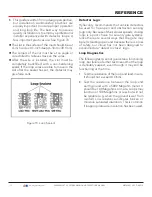
Connect one lead of the power supply to one
lead of the lock’s coil. See Figure 67
.
Figure 67. Lock Installtion- High Voltage
2.
Connect the other lead of the lock’s coil to NO
on USER 1 RELAY.
3.
Connect the COM on USER 1 RELAY to the
second lead wire in the power supply (115V
or 230V).
4.
Set the User Relay function in the Installer
Menu to RL1 - 6.
See Figure 68.
High voltage
High voltage
115VAC
230VAC
Lock
USER 1 RELAY
NO
COM
POWER SUPPLY
1
2
3
NOTICE
Connect to NC on USER 1 RELAY if installing
a maglock.
109
| www.hysecurity.com
SWINGSMART DC PROGRAMMING AND OPERATIONS MANUAL
MX3640-01 REV. D ©2018


