INSTALLATION
GATE BRACKET AND LINKAGE ARMS
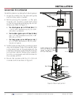
Installing the Gate Bracket
1.
Secure the gate to prevent movement.
2.
Determine the proper position of the gate
bracket. Use Figure 6 and Table 2 for reference.
Hint:
Determine if you have a short, medium,
or long gate. If the X and Y dimensions in the
chart are the same as your install, set the gate
bracket at the Xg dimension. If your install does
not fit to the chart specs, use the Custom Gate
Installation formula to determine the proper
gate bracket placement.
3.
Measure and position the gate bracket so it is
level with the arm on the operator. Clamp the
gate bracket to the horizontal cross member.
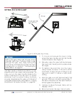
Figure 6. Installing the Gate Bracket
CAUTION
Consider positioning the operator so existing
conduit exits through the cutout in the
SwingSmart base plate. Cutting small holes
in the base plate for pre-existing conduit is
permissible, but not recommended because
it can impair the strength of the chassis and
void the Limited Warranty.
Hinge Center
X
Xg
Y
Table 2. Gate Bracket Installation
Dimensions
Short Gate Installation:
For gates up to 10 feet (3 meters)
X
Y
Xg
10.5" (27cm)
14" (36cm)
23.5" (60cm)
18" (46cm)
27.5" (70cm)
20" (51cm)
29.5" (75cm)
Medium Gate Installation:
For gates up to 13 feet (4 meters)
X
Y
Xg
12" (31cm)
22" (56cm)
33" (84cm)
24" (61cm)
35" (89cm)
28" (71cm)
39" (99cm)
Long Gate Installation:
For gates up to 20 feet (6 meters)
X
Y
Xg
15" (38cm)
30" (76cm)
44" (112cm)
35" (89cm)
49" (124cm)
40" (101cm)
54" (137cm)
Custom Gate Installation:
X
Y
Xg
–
–
X + Y - 1
29
| www.hysecurity.com
SWINGSMART DC PROGRAMMING AND OPERATIONS MANUAL
MX3640-01 REV. D ©2018


