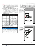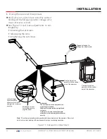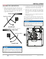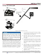
POWER
Connecting the Peripherals to Solar Operators
Figure 22. Connecting DC Power
COM
COM
COM
COM
COM
COM
COM
COM
STOP
OPEN
RADIO
CLOSE
OPEN
OPEN
PARTIAL
SENSOR
2
SENSOR
3
SENSOR
1
EXIT
LOOP
BLOCK
EXIT
IN OBS
LOOP
OUT OBS
LOOP
CENTER
LOOP
SENSOR
COM
+ 24 V
EMERG
OPEN
SHOW
LEDs
COMMON
TERMINALS
HY-5B
FREE EXIT
HY-5B
INSIDE LOOP
HY-5B
OUTSIDE
LOOP
HY-5B
CENTER
LOOP
RS-485
COMMUNICATION
USB
PORT
USER RELAY 1
Electro-mechanica
l
USER
RELAY
2
Solid state
24VDC
24VDC
12VDC
12VDC
Press button to
light active inputs
COM
B
A
DUAL GATE
COM OPEN +24V
RADIO OPTIONS
S1
COM NO
USER2
DC
Amp Draw on Power Supplies
Two power supplies are available:
24VDC and 12VDC
A maximum draw of 1A is available
for each power supply.
NOTE:
The 24VDC power supply has
four terminals that can be used in any
combination to draw the available 1A
maximum.
For example:
Amp Draw & Accessories connected to 24VDC
0.50A = Three photo eyes (for entrapment protection)
0.25A = Keypad with light
0.015A = Three HY-5B detectors
0.76A
46
| www.hysecurity.com
SWINGSMART DC PROGRAMMING AND OPERATIONS MANUAL
MX3640-01 REV. D ©2018

