SMART DC CONTROLLER
PRELIMINARY TESTING OF INPUTS
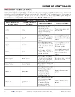
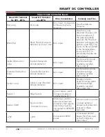
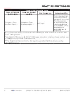
All the control device inputs listed in Table 13 are shown as a single input. The second wire is connected
to a Common Terminal Bus (COM) on the Smart DC Controller. The Fire Department Open input is
an exception and requires a +24 Volt input as well as activation in the Installer Menu (item FO). For
convenience a +24V terminal is located next to the EMERG OPEN terminal.
Table 13. SDC Controller Inputs
Smart DC Terminal
UL 325 - 2016
Smart DC Terminal
pre-2016
Wire Connections
Comonly used for...
COM
COM
All user inputs are
energized when
connected to common
except Emergency
Open.
Powering sensors and
accessories
Stop
Stop *
Normally Closed
(N.C.). input. Jumper to
Common if not being
used.
Line of sight, external
stop button or 3-button
station
Open
Open *
Normally Open (N.O.)
input. DO NOT use for
radio or remote access
controls
Line of sight, external
open button or
3-button station.
Close
Close
N.O. input. DO NOT
use for radio or remote
access controls
Line of sight, external
connection for a close
button or 3-button
station.
Radio Open
Radio Open
N.O. input. For radio
/ remote open device:
Access RO in the User
Menu and set to 1.
Remote access controls
or radio controls.
Open Partial
Open Partial
Not used in swing gate
operators.
Sensor 2
Eye Open
N.C. input. Connection
for Photo Eye Open
direction. Type
of sensor used is
programmable in
Installer Menu (S2).
External Entrapment
Sensor
Sensor 3
Eye Close
N.C. input. Connection
for Photo Eye Close
direction. Type
of sensor used is
programmable in
Installer Menu (S3).
External Entrapment
Sensor
85
| www.hysecurity.com
SWINGSMART DC PROGRAMMING AND OPERATIONS MANUAL
MX3640-01 REV. D ©2018

