background image

Important Safety Information

WARNING

A moving gate or barrier arm, bollard, or wedge can cause serious injury or death. It is therefore incumbent on the site designer, installer, 
and property owner to ensure that these hazards are mitigated and the public is warned of the existence of a potential hazard. Read all the 
product safety information prior to installation. Verify the gate operator is installed to comply with all safety standards and local and federal 
regulations and is designated for its proper usage class. For more information, refer to your gate operator's product manual. 

To reduce the risk of injury or death: 

1.  READ AND FOLLOW ALL INSTRUCTIONS. Read the gate operator’s product manual and review all the product labels and literature  prior to 

installing, operating, or maintaining the automatic gate operator.

2.  Never let children operate or play with gate controls. Keep all remote controls, especially radio transmitters, away from children.  Do not allow 

children to play on or around the gate or gate operators.

3.  Always keep people and objects away from the gate. NO ONE SHOULD CROSS THE PATH OF THE MOVING GATE. Start the gate operator 

 only when a gate’s travel path is clear. 

4.  Test the gate operator monthly. The gate MUST reverse on contact with a rigid object or stop when an object activates the non-contact 

 sensors. After adjusting the force or the limit of travel, retest the gate operator. Perform routine tests of the entrapment protection  sensors, 

such as photo eyes and edge sensors. Failure to adjust and retest the gate operator properly can increase the risk of injury or death.

5.  Use the emergency release only when the gate is not moving.
6. 

+%%0Ÿ'!4%3Ÿ02/0%2,9Ÿ-!).4!).%$Ÿ2EADŸTHEŸPRODUCTŸMANUALSŸ(AVEŸAŸQUALIÚEDŸSERVICEŸPERSONŸMAKEŸREPAIRSŸTOŸGATEŸHARDWAREŸANDŸREPLACEŸ

batteries in accessory or entrapment protection sensory devices on a regular basis.

7.  The automated gate entry is for vehicle use only. Pedestrians must use a separate entrance. Make sure a separate walk-through  entrance is 

nearby. Make certain a clear pedestrian path is designated and signs direct pedestrians to the walk-through gate. 

8.  Install the supplied WARNING signs on the inside and outside of the gate or barrier gate/operator so they are clearly visible from both  the 

secure and public sides. Installing the signs is a requirement for UL 325 compliance.

9. 

5SEŸMONITOREDŸSENSORSŸFORŸPROTECTIONŸAGAINSTŸENTRAPMENTŸASŸSPECIÚEDŸINŸTHEŸCURRENTŸ5,ŸŸ3TANDARDŸFORŸ3AFETYŸ3EEŸ'ENERALŸ%NTRAPMENTŸ

0ROTECTIONŸ0ROVISIONSŸPERŸ5,ŸŸ4ABLEŸŸONŸPAGEŸ

NOTICE:

 Extensive safety information exists in the gate operator product manuals. Be aware and read all safety information, labels and 

signage that is shipped with your gate operator to ensure quality site design, proper set up for functional gate operation and pedestrian safety. 
This document is a supplement, and as such, focuses on the differences in monitoring external entrapment protection sensors and the 
application of external sensors. Be sure to read all the information provided with your product manuals.

S

AFETY

 I

NFORMATION

 S

PECIFIC


TO

 M

ONITORED

 E

NTRAPMENT

The following is found in HySecurity 

Programming and Operations Manuals,

 but re-iterated here. Before installing the 

gate operator:

Mount access control devices beyond reach of the gate. The control devices that operate the gate must:

• 

Be located in a clear line of sight to the gate. Locate controls (Open, Close, Stop/Reset) where a user will have a clear view of the gate. 

NOTE:

 An exception for Emergency Access Control devices exists. An EAC device accessible by authorized 

PERSONNELONLY EGÞREPOLICE%-3MAYBEPLACEDATANYLOCATIONWITHINTHELINEOFSIGHT

• 

Be mounted beyond 6 feet (183 cm) of the gate to prevent users from touching or accessing the gate while operating the controls. People 

attempting to access the controls by reaching through or around the gate can be seriously injured or killed by the moving gate.

• 

Connect radio and other remote access (non-resetting controls) to the RADIO OPTIONS terminal. 

Install an automatic operator only on gates that comply with ASTM F2200 Gate and Fence Standards and the usage class of the gate. Screen or 

enclose openings in  the gate per UL 325 Standards for Safety which include:

• 

All horizontal slide gates must guard or screen openings from the gate’s base support to a minimum height of 6 feet (183 cm) above the 

ground. This must prevent a sphere of 2¼-inches (57 mm) in diameter from passing through an opening in the gate or the adjacent fence that 

is covered in the gate’s open position.

• 

All exposed pinch points are eliminated or guarded.

• 

Physical stops must exist in the gate construction to prevent over-travel in both directions and, for slide gates, guide posts must  be installed 

to prevent the gate from falling in the event of a roller failure. Guarding must be supplied for exposed rollers.

• 

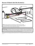
External entrapment protection sensors must be used wherever the risk of entrapment exists. Refer to page 5. 

SAVE THESE INSTRUCTIONS

2


  D0726 Rev. C 

UL 325 - 2016 HySecurity Monitored Sensors 


©

 2016  www.hysecurity.com

Summary of Contents for UL 325-2016

Page 1: ...ing Normally Closed NC sensors to conform to UL 325 monitored entrapment protection requirements PPROVED SENSORS RECOMMENDED FOR USE WITH Y3ECURITY GATE OPERATORS ARE SPECI ED IN THIS DOCUMENT For mor...

Page 2: ...THE CURRENT 5 3TANDARD FOR 3AFETY 3EE ENERAL NTRAPMENT 0ROTECTION 0ROVISIONS PER 5 4ABLE ON PAGE NOTICE Extensive safety information exists in the gate operator product manuals Be aware and read all...

Page 3: ...3URYLVLRQV SHU 8 7DEOH 12 8VDJH ODVV HVLJQDWHG DWH 2SHUDWRU 3URYLVLRQV 12 LDJUDP 7 SLFDO 6OLGH DWH 6LWH VVHVVPHQW 13 LDJUDP 6OLGH ULYHU QSXWV 3URJUDPPLQJ 14 LDJUDP 6ZLQJ DWH 6LWH VVHVVPHQW 15 LDJUDP 6...

Page 4: ...6 set at the factory UL 325 Entrapment Protection Device Monitoring Required Normally Closed NC sensors tested approved Three SENSOR Inputs on Controller NSTALLER ENU CON GURABLE Build Year BY factory...

Page 5: ...FOR SQUARE POST 10K Resistor Miller Edge Type B2 Gate Edge Module GEM 104 Edge Interface Module Normally Closed MX4037 MX3983 KIT Wired Gate Edge Sensor MGO 2E 05 T2 Square and Channel mount Edge 3 s...

Page 6: ...3 VEHICLE DETECTOR VEHICLE DETECTOR VEHICLE DETECTOR STOP BUZZER FREE EXIT INSIDE OBSTR OUTSIDE OBSTR SHADOW RESET WIEGAND HySecurity COM NO MX000585 VERSION S N RS232 DISPLAY VEHICLE DETECTOR COM COM...

Page 7: ...ontroller Location of Sensor Inputs on Controller Installer Menu Item Codes Smart Touch Controller STC Hydraulic gate operators Smart Touch Display Input Current Silk Screen Label 2016 Silk Screen Lab...

Page 8: ...ept to a minimum and then install your HySecurity gate operator 2 Install NC sensors Install contact and non contact sensors edge sensors and photo eyes for all entrapment zones HySecurity gates monit...

Page 9: ...rammed to a non zero setting before the gate will move NOTE The gate operator will not automatically cycle unless an indication is received that the appropriate number of external entrapment protectio...

Page 10: ...direction for a 2 second interval and then resumes moving in the open direction if the photo eye clears within 5 seconds Sensor 1 2 or 3 Sensor COM COM 24V GR 0 FULL OPEN GATE EDGE LOGIC 0 Edge rever...

Page 11: ...e use of additional safety designs components It is up to the gate system designer and installer to assess appropriate safety design and components above and beyond minimum 5 AND 34 STANDARDS LWAYS CH...

Page 12: ...es 406 mm and does not have a pinch point between moving parts by virtue of the operator s design or as a result of INSTALLATION IN ACCORDANCE WITH INSTRUCTIONS SUPPLIED WITH THE OPERATOR AS SPECI ED...

Page 13: ...photo eye Normally Closed EMX Industries Type B1 MX3990 IRB MON Dist 100 ft Thru beam photo eye Normally Closed EMX Industries Type B1 NOTE At minimum external entrapment protection sensors must be i...

Page 14: ...ED TO A NON ZERO NUMBER NOTE The software requires CON RMATION OF ALL MONITORED 3 3 2 inputs before allowing the gate to move An example of the connections for an Edge and a Photo Eye monitored sensor...

Page 15: ...Operators P N 2016 Monitored Sensors Sensor Type Output Manufacturer UL 325 Recognized MX3981 MX3983 Wired Gate Edge Sensor MGR20 2U 05 T2 Round Wraparound edge FT FOR ROUND POST 10K Resistor Miller E...

Page 16: ...nputs must be CON GURED An example of the connections for an Edge and a Photo Eye monitored sensors and the Installer Menu settings for the Smart Touch Controller STC are shown in Diagram 4 The wiring...

Page 17: ...t entrapment HySecurity barrier arms provide features for object detection For more information refer to the gate operator s product manual MX3186 01 02 03 Photo eye receiver not SHOWN IN ILLUSTRATION...

Page 18: ...E CHARGER AC LOSS LOCK INTERLOCK EMERG CLOSE FIRE DEPT OPEN 2 3 4 5 6 7 8 9 10 11 12 14 15 16 17 18 19 20 21 22 23 24 Smart Touch Controller LIMIT DUAL GATE RADIO OPTIONS DRIVE POWER RS485 MOTOR USER...

Page 19: ...ar in the following chart For a full list see page 5 EXAMPLE External Entrapment Protection Sensors Normally Close Contact Compatible with HySecurity Gate Operators P N 2016 Monitored Sensors Sensor T...

Page 20: ...LOSE 1 OPEN PARTIAL INTERLOCK OPEN TIME CLOCK OPEN FREE EXIT DETECTOR DISABLE EXIT DETECTOR DISABLE CLOSE TIMER INSIDE OBSTRUCTION VEHICLE DETECTOR OUTSIDE OBSTRUCTION VEHICLE DETECTOR SHADOW RESET VE...

Page 21: ...RAW IN ZONE 4 NY GAP LARGER THAN o MM between gate and fixed objects must be protected Install wrap around edge sensors where gap between post and gate creates a DRAW IN ZONE After wiring your extern...

Page 22: ...Photo eye Secure Side Photo eye TRANSMITTER OUNT ACCESS CONTROL DEVICES AT LEAST FT M BEYOND THE GATE Reflector for Photo Eye After wiring your external entrapment protection sensors to the Controlle...

Page 23: ...OOTING The Smart Touch Controller reports system malfunctions using three simultaneously occurring methods Codes presented on its display alert fault or error CTIVATION OF A BUZZER WHICH EMITS A SERIE...

Page 24: ...gn photo eye Replace photo eye battery if needed ALERT ACTION BLOCKED GATE EDGE Open or Close 2 5 chirps indicating that the command cannot be initiated Operator received command to run open but movem...

Page 25: ...OST 10K Resistor Miller Edge Type B2 Gate Edge Module GEM 104 Edge Interface Module Normally Closed MX3982 MX3983 Wired Gate Edge Sensor MGS20 2U 05 T2 Square Wraparound edge FT FOR SQUARE POST 10K Re...

Page 26: ...5 VERSION S N RS232 DISPLAY VEHICLE DETECTOR COM COM A B RPM COM OPEN S 1 24V 24V STATUS LED WIRED EDGE SENSOR WITH GEM GATE EDGE MODULE 1 Turn OFF power 2 Connect the Green NC relay wire from GEM to...

Page 27: ...E FIRE DEPT OPEN 2 3 4 5 6 7 8 9 10 11 12 14 15 16 17 18 19 20 21 22 23 24 Smart Touch Controller LIMIT DUAL GATE RADIO OPTIONS DRIVE POWER RS485 MOTOR USER 1 USER 2 USER 3 VEHICLE DETECTOR VEHICLE DE...

Page 28: ...ZER FREE EXIT INSIDE OBSTR OUTSIDE OBSTR SHADOW RESET WIEGAND HySecurity COM NO MX000585 VERSION S N RS232 DISPLAY VEHICLE DETECTOR COM COM A B RPM COM OPEN S 1 24V 24V STATUS LED PHOTO EYE TRANSMITTE...

Page 29: ...4 5 6 7 8 9 10 11 12 14 15 16 17 18 19 20 21 22 23 24 Smart Touch Controller LIMIT DUAL GATE RADIO OPTIONS DRIVE POWER RS485 MOTOR USER 1 USER 2 USER 3 VEHICLE DETECTOR VEHICLE DETECTOR VEHICLE DETECT...

Page 30: ...CLE DETECTOR SHADOW RESET VEHICLE DETECTOR SENSOR 1 SENSOR COM DO NOT USE SENSOR 2 DO NOT USE SENSOR 3 DO NOT USE CHARGER AC LOSS LOCK INTERLOCK EMERG CLOSE FIRE DEPT OPEN 2 3 4 5 6 7 8 9 10 11 12 14...

Page 31: ...RUCTION VEHICLE DETECTOR SHADOW RESET VEHICLE DETECTOR SENSOR 1 SENSOR COM DO NOT USE SENSOR 2 DO NOT USE SENSOR 3 DO NOT USE CHARGER AC LOSS LOCK INTERLOCK EMERG CLOSE FIRE DEPT OPEN 2 3 4 5 6 7 8 9...

Page 32: ...DO NOT USE SENSOR 3 DO NOT USE CHARGER AC LOSS LOCK INTERLOCK EMERG CLOSE FIRE DEPT OPEN 2 3 4 5 6 7 8 9 10 11 12 14 15 16 17 18 19 20 21 22 23 24 Smart Touch Controller LIMIT DUAL GATE RADIO OPTIONS...

Page 33: ...Page intentionally left blank...

Page 34: ...Page intentionally left blank...

Page 35: ...TION MADE TO PRODUCTS WILL VOID THE WARRANTY UNLESS THE MODI CATIONS ARE APPROVED IN WRITING BY Y3ECURITY in advance of the change this exclusion does not apply to normal installation of approved acce...

Page 36: ...Gate Inc Federal copyright law prohibits the reproduction distribution or public display of copyrighted materials without the express written permission of the copyright owner unless fair use or other...

Reviews: