• Occupancy Sensor
• Brake System Sensors
• Pump Status
• Hydraulic Control Inputs
• E-Hydraulic Valves
• Hydraulic Sensors
• System Voltages
• Steering Position Sensors
The following topics describe the Diagnostics sub-
menus.
FAULT CODE LOG
Use this submenu to view the 20 most recent fault
codes for any of these devices: Master Controller,
Traction Controller 1 or 2, Pump Controller, Light
Controller, E-Hydraulics, Impact, or Display.
NOTE:
Pressing the Scroll Back Key or Scroll
Forward Key returns the user to the Diagnostics
Menu list.
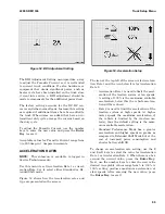
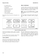
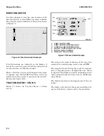
Figure 72 shows how the devices appear on the dis-
play. The Master Controller's fault log displays
first.
Figure 72. Fault Log Menu Order
Press the 2 Up Arrow soft key to view a previous
log or press the 3 Down Arrow soft key to view the
next log.
To clear the fault log for the device being viewed,
press the 4 soft key near the Trash Can Icon.
Fault Log Details
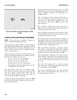
Each log entry presents the fault code, the number
of occurrences, the truck hour at the time of the
first occurrence, the system time at the first occur-
rence, and the system time at the last occurrence.
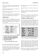
The system shows either the system time of the oc-
currences or the hour meter reading of the occur-
rences as shown in Figure 73. Press the 1 soft key
next to the hour glass or clock Icon in the upper left
corner of the display to switch between display of
system times or hour meter readings.
Diagnostics Menu
2200 SRM 1336
110
Summary of Contents for A1.3-1.5XNT
Page 6: ... THE QUALITY KEEPERS HYSTER APPROVED PARTS ...
Page 9: ...Figure 3 Technician Flowchart Sheet 1 of 4 2200 SRM 1336 Menu Flowchart 3 ...
Page 10: ...Figure 3 Technician Flowchart Sheet 2 of 4 Menu Flowchart 2200 SRM 1336 4 ...
Page 11: ...Figure 3 Technician Flowchart Sheet 3 of 4 2200 SRM 1336 Menu Flowchart 5 ...
Page 12: ...Figure 3 Technician Flowchart Sheet 4 of 4 Menu Flowchart 2200 SRM 1336 6 ...
Page 123: ......
Page 124: ...TECHNICAL PUBLICATIONS 2200 SRM 1336 2 14 8 13 4 13 12 12 3 12 12 11 ...

