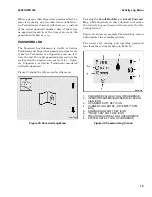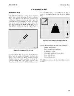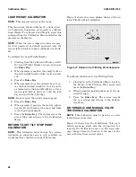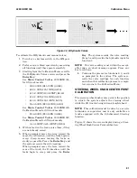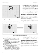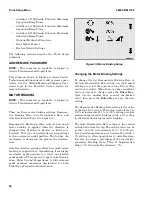
Figure 33. Steering Wheel Knob Center Point
To calibrate the Steering Wheel Knob Center Point:
1.
Starting from the Calibration Menu, scroll to
the Steering Wheel Knob Center Point
screen and press the Enter Key.
2.
When prompted, position the steering wheel
in the position that will drive the lift truck
straight ahead.
3.
Press the Enter Key. The system records
the steering wheel position as the new center
point and returns to the Calibration Menu.
STEER AXLE POSITION CALIBRATION
NOTE:
This calibration must be done by a service
technician or supervisor and is only available on
trucks equipped with the Synchronized Steering
function or dual traction motors.
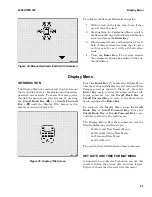
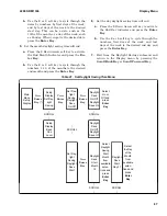
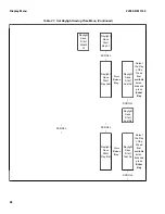
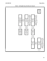
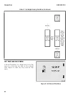
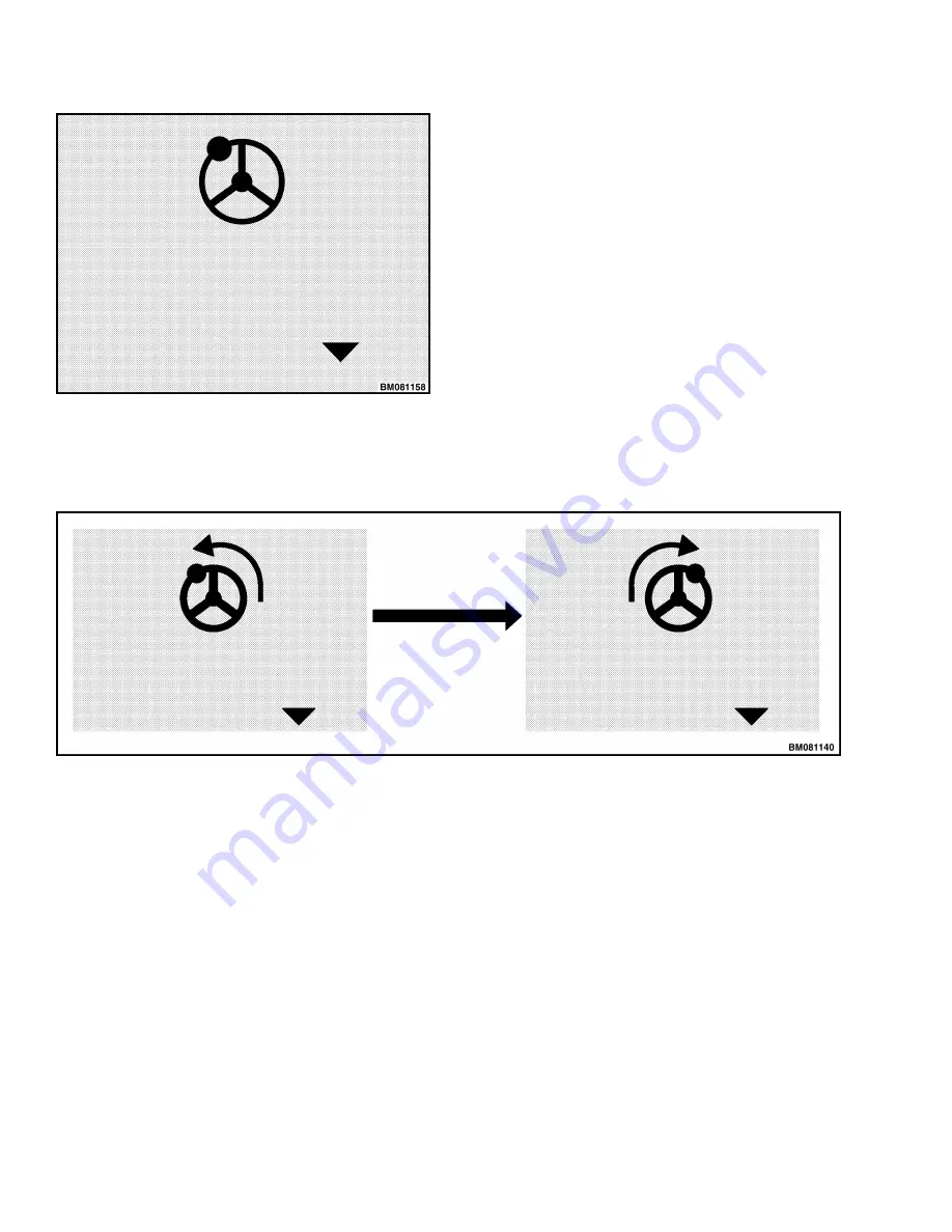
Figure 34 shows the screens that appear while cali-
brating the Steer Axle Position.
Figure 34. Calibrating Steer Axle Position
To calibrate the Steer Axle Position:
1.
Starting from the Calibration Menu, scroll to
the Steer Axle Position screen and press the
Enter Key.
2.
When prompted, turn the steering wheel
counterclockwise until the axle hits the stop.
3.
Press the Enter Key.
4.
When prompted, turn the steering wheel
clockwise until the axle hits the stop.
5.
Press the Enter Key. If the settings are ac-
ceptable, the system records the steer posi-
tions and returns to the Calibration Menu. If
the settings are outside of the acceptable
range, an X appears over the Calibration
Icon. Press the Enter Key and the system
will prompt the user to repeat steps 2 – 5.
MANUAL HYDRAULICS CALIBRATION
NOTE:
This calibration must be done by a service
technician or supervisor and is only available on
trucks equipped with manual hydraulics.
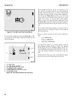
Figure 35 shows the screen menu the system dis-
plays during this calibration.
Calibration Menu
2200 SRM 1336
82
Summary of Contents for A1.3-1.5XNT
Page 6: ... THE QUALITY KEEPERS HYSTER APPROVED PARTS ...
Page 9: ...Figure 3 Technician Flowchart Sheet 1 of 4 2200 SRM 1336 Menu Flowchart 3 ...
Page 10: ...Figure 3 Technician Flowchart Sheet 2 of 4 Menu Flowchart 2200 SRM 1336 4 ...
Page 11: ...Figure 3 Technician Flowchart Sheet 3 of 4 2200 SRM 1336 Menu Flowchart 5 ...
Page 12: ...Figure 3 Technician Flowchart Sheet 4 of 4 Menu Flowchart 2200 SRM 1336 6 ...
Page 123: ......
Page 124: ...TECHNICAL PUBLICATIONS 2200 SRM 1336 2 14 8 13 4 13 12 12 3 12 12 11 ...


