PINION REPAIR
CAUTION
Steering functions will not operate properly if pin-
ions are not aligned properly with steer swivel
(control handle) and drive tire.
Remove and repair the pinion assemblies as necessary.
Upper Pinion
After removing the articulating shaft, the upper pinion can
be removed from the support base for repair.
1.
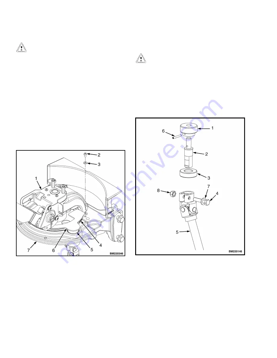
Remove two screws, two washers and gear cover plate
from the steer support. See Figure 10.
NOTE:
Disassemble only as necessary for repair. Pinion
assembly parts are not individually repairable, but the as-
sembly may be replaced as a whole.
1. STEER SWIVEL
2. WASHER
3. SCREW
4. STEER SUPPORT GEAR
5. PINION GEAR
6. GEAR COVER PLATE
7. SUPPORT BASE
Figure 10. Gear Cover
2.
Lift the upper pinion assembly from the support base.
Remove bearing from shaft. Drive pin from gear and
remove gear from shaft as necessary. See Figure 11.
3.
Install gear to shaft as removed. Align hole in gear
with hole in shaft and install retaining pin. Install bear-
ing onto shaft.
CAUTION
Ensure that pinion shaft notch and steer swivel
(control handle) are aligned in the "straight
ahead" position before continuing.
4.
Install the pinion into the support base with the notch
aligned with the steer swivel (control handle) in the
straight ahead position. Position the gear cover to the
support base and install two screws and washers to se-
cure.
1. PINION GEAR
2. PINION SHAFT
3. BEARING
4. CAPSCREW
5. ARTICULATING
SHAFT
6. RETAINING PIN
7. WASHER
8. LOCK NUT
Figure 11. Upper Pinion Assembly
Articulating Shaft and Pinions (EPAS)
1600 SRM 1637
12


