background image

MAINTENANCE

94

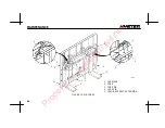
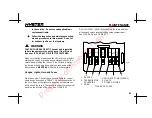
FIGURE 26. ENGINE COMPARTMENT FUSES AND RELAYS, GM 4.3L EPA COMPLIANT

ENGINE (H135---155XL, H135---155XL

2

AND H155XLS [G006] TRUCKS ONLY)

HO190288

1. FUSE PANEL

2. MOUNTING BRACKET

F1. 20 AMPS

F2. 5 AMPS

F3. 15 AMPS

F4. 15 AMPS

F5. SPARE

F6. SPARE

R1. STARTER RELAY

R2. POWER RELAY

R3. FUEL PUMP RELAY

R4. SPARE

Property of American Airlines

Summary of Contents for CHALLENGER H100XL

Page 1: ... THIS MANUAL FROM THIS UNIT H70XL H80XL H90XLS H90XL H100XL H110XL G005 H135XL H135XL2 H155XL H155XL2 H155XLS F006 G006 DO NOT REMOVE THIS MANUAL FROM THIS UNIT HYSTER COMPANY PART NO 897364 P r o p e r t y o f A m e r i c a n A i r l i n e s ...

Page 2: ...ortist Fortenst Pacesetter VSMt DuraMatcht Spectrumt TouchPointt TouchControlt EZXchanget HSMt ReachStackert SitDrivet StanDrivet Multiquipt and Unisourcet are trademarks of Hyster Company in the united States and or in certain countries where rights in unregistered trademarks are recognized Hyster Company products included in this document may be covered by U S Patenet No 6 684 148 and other U S ...

Page 3: ... the operator can see hear and has the physical and men tal ability to operate the equipment safely Various laws and regulations require the employer to train lift truck operators These laws and regulations include Occupational Safety and Health Act USA Canada Material Handling Regulations NOTE A comprehensive operator training program is available from HYSTER COMPANY For further details contact y...

Page 4: ...ety Standard For Low Lift And High Lift Trucks publications from government safety agencies government insurers private insurers and private organizations Example Accident Prevention Manual For Industrial Operations from the National Safety Council NOTE Hyster lift trucks are not intended for use on public roads NOTE The following symbols and words indicate safety information in this manual WARNIN...

Page 5: ...NG TECHNIQUES 35 Basic Operating Procedures 35 Driving And Direction Changes 38 Operator Presence System 39 Inching 40 Steering Turning 40 Load Handling General 42 Load Handling Lifting Lowering And Tilting 43 Load Handling How To Engage And Disengage A Load 46 Load Handling Traveling 48 HIGHWAY TRUCKS RAILROAD CARS AND DOCKS 51 ATTACHMENTS 52 STOPPING 53 PARKING 53 MAINTENANCE 55 GENERAL 55 HOW T...

Page 6: ...110XL 96 Control Levers and Pedals 97 Lift System Operation 98 Inching Brake Pedal 98 Service Brakes 99 Parking Brake 99 Steering System 99 HOW TO ADD FUEL TO THE LIFT TRUCK 100 Liquified Petroleum Gas LPG 100 Gasoline or Diesel Fuel 103 WHEELS AND TIRES 104 How To Repair A Pneumatic Tire 104 Remove The Wheels From The Lift Truck 104 Remove The Wheel From The Tire 105 Install The Wheel In The Tire...

Page 7: ...CONTENTS 5 Remove The Tire From The Wheel 123 Install The Tire On The Wheel 125 OPERATING PROCEDURES FOR A NEW OR REBUILT ENGINE 127 P r o p e r t y o f A m e r i c a n A i r l i n e s ...

Page 8: ...MODEL DESCRIPTION 6 A WARNING label with this information must be on the lift truck P r o p e r t y o f A m e r i c a n A i r l i n e s ...

Page 9: ...WARNING 5 NOTES P r o p e r t y o f A m e r i c a n A i r l i n e s ...

Page 10: ...HT 3 STEERING AXLE 4 DRIVE AXLE 5 PARKING BRAKE 6 MAST 7 FORKS 8 CARRIAGE 9 LOAD BACKREST EXTENSION 10 SEAT BELT AND HIP RESTRAINT BRACKET 6 6 9 9 1 1 2 2 3 3 4 4 5 5 10 10 7 7 8 8 FIGURE 1 MODEL VIEW SHOWING MAJOR COMPONENTS H135 155XL P r o p e r t y o f A m e r i c a n A i r l i n e s ...

Page 11: ...ssions can be equipped with two kinds of controls a MONOTROL pedal that controls both the for ward and reverse operation of the powershift trans mission and the speed of the engine a direction control lever near the left side of the steering wheel that controls the forward and reverse operation of the powershift transmission A separate accelerator pedal controls the engine speed The H135 155XL lif...

Page 12: ... help the operator keep the head and torso substantially within the confines of the lift truck frame and overhead guard if a tipover occurs This re straint system is intended to reduce the risk of the head and torso being trapped between the lift truck and the ground but it can not protect the operator against all pos sible injury in a tipover The hip restraint bracket will help the operator resis...

Page 13: ...n a complete nameplate SAFETY LABELS Safety labels are installed on the lift truck to give informa tion about possible hazards It is important that all safety labels are installed on the lift truck and can be read See FIGURE 3 LABEL NAMEPLATE TRUCK MODEL Serial no Approx weight NOTICE TO USER This unit was shipped incomplete from factory The U S A Occupational Safety and Health Act of 1970 and oth...

Page 14: ...S 6 TIPOVER WARNING 7 FIRE SAFETY 8 FAN WARNING 9 NO RIDERS 10 FLAMMABLE LP GAS 11 WARNING FOR PARKING BRAKE 12 MAST WARNING 13 OPERATOR PRESENCE SYSTEM SEE THE PARTS MANUAL FOR THE PART NUMBER AND LOCATION 1 7 9 5 6 8 3 11 4 10 2 12 FIGURE 3 WARNING AND SAFETY LABELS 13 P r o p e r t y o f A m e r i c a n A i r l i n e s ...

Page 15: ... H70 110XL EARLIER PRODUCTION POWERSHIFT WITH MONOTROL PEDAL POWERSHIFT WITHOUT MONOTROL PEDAL MANUAL TRANSMISSION 1 2 3 4 5 8 11 11 11 9 3 12 13 20 910 10 10 21 2119 21 18 18 15 15 15 16 16 16 17 17 17 12 14 20 22 13 12 9 P r o p e r t y o f A m e r i c a n A i r l i n e s ...

Page 16: ...0 110XL LATER PRODUCTION 12402 12402 POWERSHIFT WITH MONOTROL PEDAL POWERSHIFT WITHOUT MONOTROL PEDAL MANUAL TRANSMISSION 1 2 3 4 5 6 8 9 10 11 12 12 12 13 13 14 15 15 1516 16 16 17 17 17 19 18 18 21 21 21 22 9 9 P r o p e r t y o f A m e r i c a n A i r l i n e s ...

Page 17: ...H ELECTRONIC ENGINE CONTROL 12402 POWERSHIFT WITH MONOTROL PEDAL POWERSHIFT WITHOUT MONOTROL PEDAL MANUAL TRANSMISSION 6 8 23 7 5 4 1 10 7 3 1 2 11 14 12 13 22 21 18 15 16 17 19 18 21 21 12 12 13 15 15 16 16 17 17 9 9 23 23 P r o p e r t y o f A m e r i c a n A i r l i n e s ...

Page 18: ...DAL POWERSHIFT WITH MONOTROL PEDAL FIGURE 7 INSTRUMENTS AND CONTROLS H135 155XL F006 EARLIER PRODUCTION 11639 11639 11639 1 2 3 4 5 6 9 10 11 12 13 14 15 16 17 17 17 16 16 15 15 18 18 19 20 12 12 13 14 20 22 21 21 21 5 14 P r o p e r t y o f A m e r i c a n A i r l i n e s ...

Page 19: ...OWERSHIFT WITH MONOTROL PEDAL FIGURE 8 INSTRUMENTS AND CONTROLS H135 155XL F006 G006 LATER PRODUCTION 11639 11639 11639 1 2 3 4 5 6 9 10 11 12 12 12 13 13 14 14 14 15 15 15 16 16 17 17 17 16 19 18 18 21 21 21 22 20 20 10 11 11 P r o p e r t y o f A m e r i c a n A i r l i n e s ...

Page 20: ...IFT WITH MONOTROL PEDAL FIGURE 9 INSTRUMENTS AND CONTROLS H135 155XL WITH ELECTRONIC ENGINE CONTROL 12581 12581 12581 1 2 3 4 5 6 9 10 11 13 12 14 15 16 17 18 21 22 7 15 15 10 16 16 17 17 12 12 13 14 14 19 11 20 20 21 21 23 23 11 23 P r o p e r t y o f A m e r i c a n A i r l i n e s ...

Page 21: ...NSTRUMENTS ITEM NO ITEM FUNCTION 1 Hour Meter The hour meter operates when the key switch is in the ON position Periodic Maintenance recommendations are based on these hours 2 Coolant Temperature Gauge Indicates engine coolant temperature when the key switch is in the ON position During normal operation the needle will indicate in the green zone of the gauge Do not continue to operate the lift tru...

Page 22: ... is ON at engine speeds above idle CAUTION 5 Warning Light Engine Oil Pressure The red light is ON when the key switch is in the START position CAUTION Stop the engine immediately if the light is ON when the engine is running 6 Warning light Powershift Transmission Oil Temperature The red light is ON when the key switch is in the START position Do not continue to operate the lift truck if the ligh...

Page 23: ...l the fault is corrected A trained service person must make repairs and adjustments if this light is ON when the engine is running NOTE XL2 lift trucks with gasoline engines only 8 Warning Light Oil Pressure for Clutch Manual Transmission H70 110XL CAUTION The red light is ON when the oil pressure in the clutch system is too low for continued operation The red light is ON when the key switch is ON...

Page 24: ...ition OFF position Deenergizes all electric circuits except for the horn and headlights No 2 Position ON position Energizes all electric circuits except the starter circuit The key switch will be in this position during normal operation No 3 Position START position Energizes the starter motor for starting the engine A spring returns the key to position No 2 ON position when the key is released NOT...

Page 25: ...transmission in NEUTRAL Use your finger to release the lock on the lever when the lever is moved to release the parking brake Always apply the parking brake when leaving the lift truck WARNING 13 Direction Control Lever H70 110XL H135 155XL The direction control for the transmission is to the left of the steering column The direction control lever is used on units with a manual transmission and th...

Page 26: ...e lever controls the four speed ranges of the manual transmission 14 Range Lever Powershift Transmission H135 155XL Only The range lever is to the left of the steering column The lever controls the two speed ranges of the powershift transmission 15 Lift Lower Control Lever The lift lower control lever is the first lever to the right of the steering wheel Pull backward on the control lever to raise...

Page 27: ...t be pushed to the right before operating the auxiliary function Two Function Operation The lever is spring loaded to the left and will operate one auxiliary function in this position The lever must be pushed to the right before operating the other auxiliary function 18 Accelerator Pedal This pedal controls the engine speed and is operated by the operator s right foot It is used on units that have...

Page 28: ... while a high engine speed is used for lifting loads Completely depressing the pedal disengages the transmission and applies the service brakes The engine can be started when the inching brake pedal is fully depressed 21 Inching Brake Pedal By varying the position of the inching brake pedal the operator can move the lift truck slowly while a high engine speed is used for lifting loads Completely d...

Page 29: ...rations 23 Latch for Tilt Steering Column Only on lift trucks equipped with a tilt steering wheel A latch located on the lower right side of the steering column allows the operator to select one of five different positions for the steering wheel Raise the latch to release the steering column Move the steering column to the selected position Release the latch to lock the steering column in position...

Page 30: ...ght Left Retract Extend SIDE SHIFT PUSH PULL ROTATE UPENDER SCOOP LOAD STABILIZER SWING FORKS SWING CLAMP L H FORK POSITIONER R H FORK POSITIONER TURN FORK FORK SPREAD Backward Forward Clockwise Counterclockwise Up Down Up Down Down Clamp Up Release Clamp Release Together Apart Horizontal Vertical FUNCTION 1 2 3 4 5 6 7 8 9 10 11 12 13 14 Right Left Right Left Together Apart Together Apart TABLE 3...

Page 31: ...work for a lift truck the load on the forks must be balanced by the weight of the lift truck The location of the center of gravity of both the truck and the load is also a factor This basic principle is used for picking up a load The abil ity of the lift truck to handle a load is discussed in terms of center of gravity and both forward and side stability Stability and Center Of Gravity The center ...

Page 32: ...over to the side easier than a loaded truck with its load in the lowered position In order for the lift truck to be stable not tip over forward or to the side the CG must stay within the area of the lift the truck represented by a triangle drawn between the drive wheels and the pivot of the steering axle CG Truck Will Tip Over Drive Axle Steering Axle If the CG moves forward of the drive axle the ...

Page 33: ...ds should be transported while centered on the centerline of the lift truck The operator must know whether or not a load is within the maximum capacity of the lift truck before the load is han dled INSPECTION BEFORE OPERATION Checks With the Engine Stopped Inspect the lift truck before use and every eight hours or daily as described in the MAINTENANCE section of this OPERATING MANUAL Before using ...

Page 34: ...r s position Gasoline Or LPG Engine 1 If the lift truck uses LPG fuel open the fuel valve on the LPG tank WARNING LPG is very flammable An odor of LPG fuel can indi cate a leak in the fuel system DO NOT start the engine until the fuel leak is repaired 2 Make sure the parking brake is applied or push on the inching brake pedal 3 If equipped put the direction control lever for the trans mission in t...

Page 35: ...rime the fuel system Push the button for the Cold Start Aid and hold it until the wire in the Cold Start Indicator is red When the Cold Start Indicator is red the glow plugs in the engine are hot Engage the starter again Push the button for the Cold Start Aid while the starter is engaged CAUTION Use only approved starting aids The use of non ap proved starting aids can result in engine damage and ...

Page 36: ...uck and the ground but it can not protect the operator against all possible injury in a tipover Make sure that the area around the lift truck is clear before starting the engine or making any operational checks Be careful when making the checks If the lift truck is station ary during a check apply the parking brake and put the transmission in NEUTRAL Proceed carefully Check the operation of the fo...

Page 37: ... locking mechanism If the truck tips travels off a dock or comes to a sudden stop the locking mechanism will be activated and hold the oper ator s lower torso in the seat Basic Operating Procedures Many people make the mistake of thinking that operating a lift truck is the same as driving an automobile This is not true It is true that some lift truck operating procedures are as simple and obvious ...

Page 38: ...must have special fire safety approval These areas must be designated to show the type of lift truck approval required for operation in the area Changes to special equipment or poor maintenance can make the lift truck lose its special approval 3 NO RIDERS A lift truck is built for only one person the operator It is dangerous for anyone to ride on the forks or anywhere else on the lift truck WARNIN...

Page 39: ...not travel with people in the platform The operator must remain at the controls Watch for over head obstructions 4 Do not drive a lift truck into an elevator unless author ized to do so Approach the elevator slowly After the ele vator is properly leveled the lift truck must be centered so that the elevator is balanced When the lift truck is in the proper position in the elevator set the brakes put...

Page 40: ...nges in speed range selection smoothly so that the load on the forks is always under control If the lift truck begins to move more slowly because of the load or a grade select a lower speed range Do not select first gear when the lift truck is moving Depress the clutch and select the lower speed range lower gear When the second gear is selected from third gear increase the en gine speed before rel...

Page 41: ...to the opposite direction of travel Operator Presence System WARNING Always make sure the parking brake is fully applied before leaving the lift truck If the operator leaves the lift truck while in operation mode a operator presence module will shift the transmission to neutral and sound an alarm for 10 seconds If the lift truck is left on a grade without the parking brake fully applied it can fre...

Page 42: ...the brakes are applied Use the accelerator pedal or MONOTROL pedal to keep the engine speed high while inching WARNING Inching requires coordinated movement of the inch ing brake pedal and the accelerator or the MONOTROL pedal New operators must practice this procedure before attempting to handle loads WARNING TRAVEL SLOWLY WHEN TURN ING Lift trucks can tip over even at very slow speeds The combin...

Page 43: ... swing and always check to make sure the tail swing area is clear before turning TAIL SWING WARNING Failure to ob serve the tail swing area when making a turn can injure or kill someone Do not turn on an incline To reduce the possibility of a tipover a lift truck must not be driven across an incline When possible keep both hands on the steering wheel During most loading or unloading opera tions th...

Page 44: ...ss than the rated capacity When such conditions exist the operator must reduce the load so that the lift truck will re main stable WARNING Do not handle a load if any loose part of it is above the load backrest or any part of the load is likely to fall 2 Handle only stable loads A load can have unstable items that can easily shift and fall on someone 3 Position each fork the same distance from the...

Page 45: ...t are not centered on the centerline of the lift truck 5 Check the condition of the driving surface Make sure the floor will support the weight of the lift truck and the load Load Handling Lifting Lowering And Tilting The LIFT and TILT functions are con trolled by separate levers See the In struments and Controls section for the correct operation The speed of the hydraulic functions is con trolled...

Page 46: ...el with the load or carriage in a raised position WARNING Keep yourself and all others clear of the lift mechanism Never allow anyone under or on the forks NEVER put hands arms head or legs through the mast or near the carriage or lift chains This warning applies not only to the operator but also a helper A helper must not be near the load or lift mechanism while the operator is attempting to hand...

Page 47: ...ted forward with a load in the raised position If the lift mechanism is raised to pick up or deposit a load keep the tilt angle in either direction to a minimum Back ward and forward tilt are helpful WARNING The lift truck can tip over forward when the load is raised Forward tipping is even more likely when tilting forward braking when traveling forward or accelerating in reverse IF THE LIFT TRUCK...

Page 48: ...hind the load being lifted are not damaged Lift the load a small distance from the floor to make sure the lift truck has the capacity to lift the load Be Careful of Forks Beyond the Load If the forks are longer than the load move the forks under the load so that the tips of the forks do not extend beyond the load Lift the load from the surface Move backward a few inches then lower the load onto th...

Page 49: ...ye level and then tilt the load forward until it is level Raise the load higher than the point where it will be placed Do not raise the load to a point below where the load is to be placed and jog the load up into posi tion This operation uses added energy particularly with an electric lift truck Be careful not to damage or move adjacent loads WARNING Move carefully and smoothly when the load is r...

Page 50: ...ted Tilt the mast fully backward to help keep the load on the forks NOTE Not every load can be lifted using only the forks of a lift truck Some loads will require a special attachment Load Handling Traveling 1 When traveling with the load lowered keep the load against the carriage and the mast tilted fully backward This will help keep the load on the forks and give good forward and side stability ...

Page 51: ... aid to the driver but are NOT driving mirrors and must NOT be used as such when operating in reverse Always look in the direction of travel to avoid damage to something or injury to someone 4 When traveling up or down a grade with a heavily loaded lift truck keep the load upgrade to maintain control When operating an unloaded lift truck on a steep grade keep the counterweight upgrade 5 Watch out ...

Page 52: ... rubber tires are designed to operate on relatively smooth firm sur faces Lift trucks with pneumatic tires can adapt to more uneven ground Always make sure you choose the smoothest route for your lift truck 8 Watch clearances especially forks mast overhead guard and tail swing A lift truck is designed to perform a wide variety of functions within limited space Make sure that the forks do not exten...

Page 53: ...er HIGHWAY TRUCKS RAILROAD CARS AND DOCKS WARNING Maintain a safe distance from the edge of docks ramps platforms and other similar working surfaces Watch the tail swing IF THE LIFT TRUCK FALLS OFF THE DOCK DO NOT JUMP OFF HOLD FIRMLY TO STEERING WHEEL BRACE YOUR FEET AND LEAN FOR WARD AND AWAY FROM THE POINT OF IMPACT Before operating in a highway truck or railroad car ob serve the following DO N...

Page 54: ... and out of the railroad car Check the condition of the driving surface Make sure the floor will support the weight of the lift truck and the load Make sure the dockboard is secured in good condition and of the proper capacity When entering a railroad car the operator can enter at an angle if the dock plate or bridge is wide enough This will reduce the turning required after entering ATTACHMENTS I...

Page 55: ...ift trans mission in NEUTRAL If the lift truck has a manual trans mission leave the gears of the transmission engaged DO NOT leave a manual transmission in NEUTRAL 4 Turn the key switch to OFF to stop the engine 5 If the lift truck must be left on an incline put blocks on the down hill side of the wheels so that the lift truck can not move If the lift truck is equipped with an LPG fuel system and ...

Page 56: ...OPERATING PROCEDURES 54 NOTES P r o p e r t y o f A m e r i c a n A i r l i n e s ...

Page 57: ...for eight hours of operation per day The time intervals must be de creased from the recommendations in the MAINTENANCE SCHEDULE for the following conditions a If the lift truck is used more than eight hours per day b If the lift truck must work in dirty operating condi tions Your dealer for Hyster lift trucks has the equipment and trained service personnel to do a complete program of in spection l...

Page 58: ...eater than the weight of the disabled lift truck The capacity of the lift truck used to move a disabled lift truck must have a load center equal to half the width of the disabled lift truck See the nameplate of the disabled lift truck for the approximate total weight The forks must extend the full width of the disabled lift truck Put the weight center of the disabled lift truck on load center of t...

Page 59: ...l forward The surface must be solid even and level when the lift truck is put on blocks Make sure that any blocks used to support the lift truck are solid one piece units NOTE Some lift trucks have lifting eyes These lift points can be used to raise the lift truck so that blocks can be installed How To Raise The Drive Tires See FIGURE 10 1 Put blocks on each side front and back of the steering tir...

Page 60: ...c jack to raise the steering tires Make sure that the jack has a capacity of at least 2 3 of the total weight of the lift truck as shown on the nameplate 3 Put the jack under the steering axle or frame to raise the lift truck Put blocks under the frame to support the lift truck FIGURE 10 PUT THE LIFT TRUCK ON BLOCKS 11704 STEERING TIRES DRIVE TIRES P r o p e r t y o f A m e r i c a n A i r l i n e...

Page 61: ...IGURE 11 MAINTENANCE POINTS FOR H70 110XL 1 2 5 6 7 8 9 10 11 12 13 14 15 16 18 19 20 21 22 23 24 25 26 27 28 29 30 31 32 35 36 37 38 10 24 21 13 10 3 4 GM V 6 ENGINE SHOWN P r o p e r t y o f A m e r i c a n A i r l i n e s ...

Page 62: ...TENANCE POINTS FOR H135 155XL H135 155XL2 H155XLS 1 2 3 5 6 7 8 9 10 11 12 13 14 15 16 17 18 19 20 21 22 24 25 26 27 28 29 30 33 34 35 36 38 14 11 10 21 13 21 23 16 GM V 6 ENGINE SHOWN P r o p e r t y o f A m e r i c a n A i r l i n e s ...

Page 63: ...F and Above SAE 10W API CC or CC SE SF SG 1 HYDRAULIC OIL H135 155XL XL2 H155XLS Powershift Transmission X C 49 7 liter 52 qt 18 C 0 F and Above SAE 10W API CC or CC SE SF SG 2 ENGINE OIL GM V 6 X C 4 7 liter 5 0 qt 18 to 40 C 0 to 104 F SAE 10W 30 API SL ILSAC GF 3 SAE 2362 ENGINE OIL DIESEL Perkins 4 2482 X C 8 5 liter 9 0 qt 15 to 40 C 5 to 104 F SAE 10W 30 10 to 50 C 14 to 122 F SAE 15W 40 API...

Page 64: ...0 API CG4 CH4 ACEA E3 E5 MIL PRF 2104G ENGINE OIL DIESEL Perkins 1104C 44 RE X C 8 0 liter 8 5 qt 15 to 40 C 5 to 104 F SAE 10W 30 10 to 50 C 14 to 122 F SAE 15W 40 API CG4 CH4 ACEA E3 E5 MIL PRF 2104G 3 POWERSHIFT TRANSMISSION OIL H70 110XL X C 17 liter 18 qt Hyster Part No 336831 3 POWERSHIFT TRANSMISSION OIL H135 155XL XL2 H155XLS X C 15 1 liter 16 qt Hyster Part No 336831 X Check C Change L Lu...

Page 65: ...2 LPG HD 5 6 COOLING SYSTEM H70 110XL Gasoline LPG X C 19 9 liter 21 0 qt 50 Water and 50 Ethylene Glycol Boron Free Anti Freeze COOLING SYSTEM H70 110XL Diesel Perkins 4 2482 X C 17 0 liter 18 0 qt 50 Water and 50 Ethylene Glycol Boron Free Anti Freeze COOLING SYSTEM H70 110XL Diesel Perkins 1004 42 X C 15 1 liter 16 0 qt 50 Water and 50 Ethylene Glycol Boron Free Anti Freeze 6 COOLING SYSTEM H13...

Page 66: ...er and 50 Ethylene Glycol Boron Free Anti Freeze COOLING SYSTEM H135 155XL XL2 H155XLS Diesel Perkins 4 2482 X C 19 9 liter 21 0 qt 50 Water and 50 Ethylene Glycol Boron Free Anti Freeze 6 CLEAN DEBRIS FROM RADIATOR CORE X Clean as needed 7 BATTERY ELECTROLYTE X Check Level See Parts Manual 8 COOLANT HOSES X Check Condition See Parts Manual SEAT BELT SEAT RAILS AND HIP RESTRAINTS X Check Condition...

Page 67: ...HTS ALARMS X Check Operation STEERING AND STEERING WHEEL POSITION LATCH X Check Operation 13 SERVICE BRAKES X X Check Operation Clean and Inspect 13 PARKING BRAKES X L Check Operation Check Condition Engine Oil 14 FORKS X X Check Condition 15 LIFT CHAINS X L X Check for Lubrication Check Condition Engine Oil SAFETY LABELS X Replace as Necessary See Parts Manual X Check C Change L Lubricate NOTE 1 ...

Page 68: ...urpose Grease See NOTE 2 18 HYDRAULIC TANK BREATHER H70 110XL X 1 Clean or Replace See Parts Manual 19 AIR FILTER X Clean or Replace See NOTE 3 See Parts Manual 19 AIR FILTER GM V 6 EPA Compliant Engine X Clean or Replace See NOTE 3 See Parts Manual 19 AIR FILTER ELEMENT GM V 6 EPA Compliant Engine C See NOTE 4 See Parts Manual X Check C Change L Lubricate NOTE 2 Multipurpose grease with 2 to 4 Mo...

Page 69: ... SPEED GM V 6 X Adjust as Required 625 to 675 rpm ENGINE IDLE SPEED Diesel All Engines X Adjust as Required 725 to 775 rpm ENGINE GOVERNED SPEED GM V 6 X Adjust as Required 2400 to 2500 rpm ENGINE GOVERNED SPEED Diesel All Engines X Adjust as Required 2400 to 2500 rpm 7 BATTERY BATTERY CASE AND CABLES X Clean 21 WHEEL NUTS DRIVE WHEELS X Check Torque All Wheel Nuts 610 to 680 N m 450 to 500 lbf ft...

Page 70: ...C 1 See NOTE 5 See Parts Manual ENGINE OIL FILTER Perkins Diesel 1004 42 C 1 See NOTE 5 See Parts Manual ENGINE OIL FILTER Perkins Diesel 1104C 44 RE C 1 See NOTE 5 See Parts Manual 23 STEERING AXLE SPINDLES L 2 Fittings Multipurpose Grease See NOTE 2 24 25 MAST Pivots L 2 Fittings Multipurpose Grease See NOTE 2 X Check C Change L Lubricate NOTE 2 Multipurpose grease with 2 to 4 Molybdenum Disulfi...

Page 71: ...AST Sideshift Carriage L 4 Fittings Multipurpose Grease See NOTE 2 24 MAST Fork Guides L As Required Engine Oil PEDALS LEVERS LINKAGES CABLES HINGES SEAT RAILS L As Required Engine Oil FINAL FUEL FILTER DIESEL C 1 See Parts Manual 28 SPARK PLUGS C 6 Check Plug Wires See Parts Manual Gap 1 6 mm 0 062 in X Check C Change L Lubricate NOTE 2 Multipurpose grease with 2 to 4 Molybdenum Disulfide P r o p...

Page 72: ...X C 1 See NOTE 6 See Parts Manual TIMING GM V 6 X Adjust as Required 0 BTDC 650 rpm TIMING Diesel All Units X Adjust as Required 16 BTDC Static VALVE ADJUSTMENT GM V 6 X Not Adjustable VALVE ADJUSTMENT Diesel All Engines Inlet Cold X Adjust as Required 0 20 mm 0 008 in X Check C Change L Lubricate NOTE 6 Both H135 155XL H135 155XL2 H155XL and H70 110XL units require a check of the crankcase breath...

Page 73: ...AND DIFFERENTIAL OIL SINGLE SPEED POWERSHIFT TRANSMISSION H70 110XL X C 7 6 liter 8 0 qt See NOTE 7 SAE 80W 90 85W 140 33 MANUAL TRANSMISSION OIL H135 155XL F006 X C 3 3 liter 3 5 qt SAE 80W 90 85W 140 34 17 SPEED REDUCER AND DIFFERENTIAL OIL MANUAL TRANSMISSION H135 155XL F006 X C 14 3 liter 15 0 qt See NOTE 7 SAE 80W 90 85W 140 X Check C Change L Lubricate NOTE7 Check the thrustscrew adjustmento...

Page 74: ...ILTER LPG C 1 See Parts Manual 35 FUEL FILTER LPG GM V 6 EPA Compliant Engine C 1 See Parts Manual 36 OIL FILTER HYDRAULIC SYSTEM C 1 See NOTE 5 See Parts Manual 37 OIL FILTER OIL CLUTCH SYSTEM H70 110XL C 1 See NOTE 5 See Parts Manual X Check C Change L Lubricate NOTE 5 Change filters on NEW trucks at the first 100 hours on the hourmeter NOTE7 Check the thrustscrew adjustmenton the differential a...

Page 75: ...UEL FILTER DIESEL X C 1 Drain Water See Parts Manual INSPECT ENGINE ELECTRICAL SYSTEM CONNECTORS AND FCVS CONNECTION X INSPECT ENGINE VACUUM AND FUEL LINES AND FITTINGS X INSPECT LOCK OFF FOR LEAKS AND ENSURE LOCK OFF CLOSING X TEST LPG GAS REGULATOR PRESSURE X X Check C Change L Lubricate NOTE 5 Change filters on NEW trucks at the first 100 hours on the hourmeter P r o p e r t y o f A m e r i c a...

Page 76: ...Light INSPECT LOW PRESSURE REGULATOR FOR OIL BUILDUP AND LEAKS X Drain Oil If Necessary CHECK AIR INDUCTION SYSTEM FOR LEAKS X CHECK MANIFOLD FOR VACUUM LEAKS X CHECK THROTTLE SHAFT FOR STICKING X CHECK INJECTORS AND RAILS FOR LEAKS X INSPECT EXHAUST MANIFOLD AND PIPING FOR LEAKS X INSPECT CATALYST INLET AND OUTLET X X Check C Change L Lubricate P r o p e r t y o f A m e r i c a n A i r l i n e s ...

Page 77: ...amaged or loose components Engine Oil See FIGURE 14 Keep the oil at the correct level as indicated on the dip stick Use the correct oil as shown in the Maintenance Schedule After the engine has stopped wait one minute before checking the oil level Air Filter See FIGURE 14 WARNING Compressed air can move particles so that they cause injury to the user or to other personnel Make sure that the path o...

Page 78: ... FLUID 3 DIPSTICK HYDRAULIC OIL FIGURE 13 MAINTENANCE POINTS H70 110XL 11725 11618 4 BREATHER HYDRAULIC TANK 5 BREATHER ENGINE 6 FILL CAP HYDRAULIC OIL 7 FILTER HEAD 1 2 3 4 5 6 7 3 H135 155XL P r o p e r t y o f A m e r i c a n A i r l i n e s ...

Page 79: ...E LPG DIESEL 1 DIPSTICK FOR ENGINE OIL 2 ENGINE OIL FILL CAP 3 AIR FILTER 4 AUXILIARY COOLANT RESERVOIR 12185 12186 5 PCV VALVE GM V 6 6 BATTERY 7 FILL CAP FUEL 8 COLD START AID DIESEL 1 2 3 4 6 7 8 1 2 3 4 5 P r o p e r t y o f A m e r i c a n A i r l i n e s ...

Page 80: ...9 FIGURE 15 AUXILIARY COOLANT RESERVOIR If the system is hot the steam and boiling coolant can cause burns DO NOT remove the cover for the radia tor when the engine is running Make sure the coolant level is between the FULL and the ADD mark on the auxiliary coolant reservoir The coolant will expand as it is heated and the level in the auxiliary coolant reservoir will increase If coolant is added u...

Page 81: ... fuels are very flammable and can burn or cause an explosion Do not use an open flame to check the fuel level or to check for leaks in the fuel system If there is a leak in the fuel system extra care must be used dur ing the repair Do not operate the lift truck until a leak is repaired Check the fuel system for leaks and the condition of parts When fuel is added to the lift truck see the section H...

Page 82: ...lates Use dis tilled water Do not fill the battery past the bottom of the internal filler neck If the battery becomes discharged and requires a boost battery to start the engine follow these procedures care fully when connecting the jumper cables a Always connect the positive boost cable to the posi tive terminal of the discharged battery and the negative to the negative b Always connect the cable...

Page 83: ...ressure so that the air pressures are equal The air pressure of the warm tires must always be equal to or greater than the air pressures specified for cold tires Check the tires for damage See FIGURE 17 Check the tread and remove any objects that will cause damage Check for bent or damaged rims Check for loose or miss ing hardware Remove any wire strapping or other mate rial that is wrapped around...

Page 84: ... is available for this series of lift trucks as an option The H135 155XL series of lift trucks normally have a pin fork Forks Adjustment Hook forks are connected to the carriage by hooks and lock pins The lock pins can be one of two types See FIGURE 18 These lock pins are installed through the top fork hooks and fit into slots in the top carriage bar Adjust the forks as far apart as possible for m...

Page 85: ...FORK LOCK PIN ASSEMBLY NEW STYLE LOCK PIN ASSEMBLY OLD STYLE LOCK PIN ASSEMBLY 1 FORK 2 LOCK PIN 3 SPRING 4 WASHER 5 WASHER 6 WEDGE 7 KNOB 8 LEVER 9 COTTER PIN 10 LOCK PIN ASSEMBLY P r o p e r t y o f A m e r i c a n A i r l i n e s ...

Page 86: ...MAINTENANCE 84 FIGURE 19 PIN FORKS 12565 1 2 3 4 5 5 1 1 2 2 3 3 4 2 1 CARRIAGE 2 FORK 3 FORK PIN 4 LOCK PIN 5 LOAD BACKREST EXTENSION P r o p e r t y o f A m e r i c a n A i r l i n e s ...

Page 87: ... without a lifting device Each fork for these lift trucks can weigh 66 kg to 183 kg 145 to 402 lb for a hook fork and 128 to 226 kg 281 to 498 lb for a pin fork FIGURE 20 REMOVE A HOOK FORK 1 3 2 1 CARRIAGE BARS 2 HOOK FORK 3 BLOCKS Hook Fork Removal Slide a hook fork to the fork re moval notch on the carriage See FIGURE 21 Lower the fork onto blocks so that the bottom hook of the fork moves throu...

Page 88: ...n the fork pin When the fork pin is installed in the car riage so that it holds the forks install the load backrest extension Engage the fork with the lock pin Inspection of Forks Mast and Lift Chains See FIGURE 21 and FIGURE 22 WARNING Never work under a raised carriage or forks Lower the carriage or use blocks and chains on the mast weld ments and carriage so that they can not move Make sure the...

Page 89: ...ATCH DAMAGE 4 HEEL OF FORK MUST BE 90 OF DIMENSION X 5 CARRIAGE 6 LOAD BACKREST EXTENSION 7 MAXIMUM ANGLE 93 8 FORK REMOVAL NOTCH 10221 8 915 mm 36 in 27 mm 1 10 in 1220 mm 48 in 37 mm 1 45 in 1830 mm 72 in 55 mm 2 15 in FORK TIP ALIGNMENT LENGTH OF FORKS 3 DIMENSION P r o p e r t y o f A m e r i c a n A i r l i n e s ...

Page 90: ...rts that fasten the side shift carriage or attach ment to the carriage are in good condition 7 Check that the lift chains are correctly lubricated Use SAE 30 engine oil to lubricate the lift chains 8 Inspect the lift chains for cracks or broken links and pins See FIGURE 22 9 Inspect the chain anchors and pins for cracks and dam age 10 Make sure the lift chains are adjusted so that they have equal ...

Page 91: ...n the lift truck See the PARTS MANUAL for the correct location of the safety labels The instructions to install the labels are also in the PERIODIC MAINTE NANCE section Operator Restraint System See FIGURE 23 The seat belt hip restraint brackets seat and mounting hood latches and floor plates are all part of the operator restraint system Each item must be checked to make sure it is attached secure...

Page 92: ... LATCH 6 HIP RESTRAINT 7 SEAT RAIL 8 FLOOR PLATE 9 HOOD 10 GAS CYLINDER 11 HINGE 11858 1 1 4 GASOLINE AND DIESEL ARRANGEMENT LPG ARRANGEMENT 2 3 6 5 9 4 6 5 10 7 7 8 11 FIGURE 23 CHECK THE HOOD AND SEAT LATCHES H70 110XL SHOWN P r o p e r t y o f A m e r i c a n A i r l i n e s ...

Page 93: ... from the retractor and retracts smoothly The seat belt must not be damaged or worn Automatic Locking Retractor ALR NOTE Lift trucks produced before November 1 2005 are equipped with the ALR type seat belts See FIGURE 24 A AUTOMATIC LOCKING RETRACTOR ALR B EMERGENCY LOCKING RETRACTOR ELR FIGURE 24 SEAT BELTS The seat belt must fasten securely Make sure the seat belt extends and retracts smoothly a...

Page 94: ...t belt assembly With the hood closed and in the locked position pull the seat belt with a sudden jerk Make sure the seat belt will not pull from the retractor assembly If the seat belt can be pulled from the retractor when it is pulled with a sudden jerk replace the seat belt as sembly With the hood in the open position make sure the seat belt will not pull from the retractor assembly If the seat ...

Page 95: ...the parking brake and put the transmission in NEUTRAL Make the checks carefully Gauges Lights Horn and Fuses Start the engine Check the gauges and lights for correct operation as described in TABLE 1 Check the operation of the horn If any of the lights or gauges do not operate cor rectly check the fuses The fuses are under the instrument panel on the left side of the cowl See FIGURE 25 On H135 155...

Page 96: ...LIANT ENGINE H135 155XL H135 155XL2 AND H155XLS G006 TRUCKS ONLY HO190288 1 FUSE PANEL 2 MOUNTING BRACKET F1 20 AMPS F2 5 AMPS F3 15 AMPS F4 15 AMPS F5 SPARE F6 SPARE R1 STARTER RELAY R2 POWER RELAY R3 FUEL PUMP RELAY R4 SPARE P r o p e r t y o f A m e r i c a n A i r l i n e s ...

Page 97: ...PERKINS 1104C 44 RE DIESEL ENGINE H135 155XL H135 155XL2 AND H155XLS G006 TRUCKS ONLY HO190289 1 LIFT PUMP RELAY 2 LIFT PUMP FUSE 10A 3 ALTERNATOR FUSE 60A 4 GLOW PLUG FUSE 60A 5 STARTER RELAY 6 GLOW PLUG RELAY P r o p e r t y o f A m e r i c a n A i r l i n e s ...

Page 98: ...ck Oil Level Oil Clutch System H70 110XL See FIGURE 28 NOTE The oil clutch system for the H135 155XL F006 lift trucks do not have a dipstick because the oil clutch uses oil from the hydraulic system Put the direction control lever in the NEUTRAL N posi tion Apply the parking brake Check oil level in the clutch housing when the engine is running at idle speed Make sure the oil is at operating tempe...

Page 99: ... SYSTEM OIL 2 DIPSTICK FOR POWERSHIFT TRANSMISSION 3 FLOOR PLATE H135 155XL 11703 11638 1 2 3 3 Control Levers and Pedals Check that the control levers for the transmission mast and attachment operate as described in TABLE 2 and TABLE 3 Check that the pedals operate as described in TABLE 2 P r o p e r t y o f A m e r i c a n A i r l i n e s ...

Page 100: ...ust raise and lower smoothly in the correct sequence NOTE Some parts of the mast move at different speeds during raising and lowering c The inner weldments and the carriage must lower completely d Raise the mast one metre three feet with a capac ity load The inner weldments and the carriage must raise smoothly Lower the mast All moving compo nents must lower smoothly e Lower the load to approximat...

Page 101: ... pedal can be hard to push when the engine is not running so that the hydraulic system is not operating Parking Brake Check the operation of the parking brake The parking brake when in good condition and correctly adjusted will hold a lift truck with a capacity load on a 15 grade 1 5 metre rise in 10 metres 1 5 ft rise in 10 ft Turn the knob on the end of the hand lever to adjust the parking brake...

Page 102: ...hen parking the lift truck more than momentarily Do not park the lift truck near heat or ignition sources Do not store LPG tanks near heat or an open flame For complete instructions on the storage of LPG fuels refer to ANSI NFPA 58 505 LPG is extremely flammable When checking or filling an LPG tank No smoking Stop engine Frost on the surface of the tank the valves or fittings and the odor of LPG f...

Page 103: ...ngine until it stops then turn the key switch to the OFF position e Release the latch that holds the LPG tank in its bracket f Raise the LPG tank from its bracket so that the quick disconnect fitting can be disconnected Re move the LPG tank from the bracket 1 FUEL VALVE TANK 2 QUICK DISCONNECT FITTING 3 FUEL GAUGE 4 PLUG NOTE Some LPG tanks have an auxiliary fill fitting instead of a plug for Item...

Page 104: ...correct position A dam aged hose or fitting can release LPG fuel and cause an explosion and fire hazard d Close the latch on the tank bracket Turn the fuel valve counterclockwise to open the fuel valve e Inspect the fuel system for leaks when the fuel valve is open Frost on the surface of the tank valves or fittings or a strong odor of LPG fuel indicates a leak Use the following procedure to fill ...

Page 105: ... vapor appears the LPG tank is full Do not fill the LPG tank more than the maximum level indicated by the liquid level indicator Immediately close the valve at the end of the supply hose i Close the vent valve on the LPG tank j Close the fuel valve on the LPG tank k Disconnect the supply hose l Stop the pump m Close the liquid outlet valve and the by pass return valve on the storage tank Gasoline ...

Page 106: ...res repaired by trained personnel only Deflate tire completely before removing the wheel from the lift truck If dual wheels are used deflate both tires Air pressure in the tires can cause the tire and rim parts to explode causing serious injury or death Always wear safety glasses Never loosen the nuts that hold the inner and outer wheel halves together when there is air pressure in the tire 1 Put ...

Page 107: ...eu matic tire can be installed on a three piece or four piece wheel for a pneumatic tire DO NOT make changes in the parts of the rim if this type of solid rub ber tire is installed instead of a pneumatic tire Changes to the parts of the rim can cause a failure of the wheel and cause an accident WARNING The type of tire and the tire pressure pneumatic tires are shown on the nameplate Make sure the ...

Page 108: ...nner and outer wheel halves together when there is air pressure in the tire WARNING Make sure all of the air pressure is removed from the tire before a wheel is disassembled Air pressure in the tires can cause the tire and rim parts to explode causing serious injury or death Keep tire tools in firm contact with wheels parts If the tool slips it can move with enough force to cause se rious injury N...

Page 109: ...side flange STEP 3 Remove the wheel halves from tire Remove the inner tube and flap SEE WARNINGS 11939 STEP 1 Remove the nuts that fasten the wheel halves together FIGURE 31 TIRE REMOVAL TWO PIECE WHEEL P r o p e r t y o f A m e r i c a n A i r l i n e s ...

Page 110: ... Remove the valve stem from the wheel STEP 4 Remove the wheel from the tire STEP 2 Put the tire tool into the slot between the lock ring and wheel rim Remove the lock ring and side flange If there is a flange seat remove it FIGURE 32 TIRE REMOVAL THREE AND FOUR PIECE WHEELS P r o p e r t y o f A m e r i c a n A i r l i n e s ...

Page 111: ...e ends of the side ring must not touch The clear ance at the ends of the lock ring must be 13 to 25 mm 0 5 to 1 0 in after it is installed If the clearance is wrong the wrong part has been used 1 Clean and inspect all parts of the wheel Paint any parts that have rust or corrosion 2 Install a new inner tube in the tire Used tubes and flaps can cause tire failure WARNING Do not lubricate the tire be...

Page 112: ...and tire Put blocks under the rim so that the rim is 8 to 10 cm 3 to 4 in above the floor Install the flange seat if used and the side flange Hold them in the correct position STEP4 Put the lock ring in the correct position on the rim Add air pressure to the tire as described in Add Air To The Tires FIGURE 33 INSTALL THE WHEEL IN THE TIRE THREE OR FOUR PIECE WHEEL P r o p e r t y o f A m e r i c a...

Page 113: ...onto the valve stem of the inner tube Make sure there is enough hose to permit the operator to stand away from the safety cage when air pressure is added to the tire Do not sit or stand by the safety cage Do not use a hammer to try and correct the position of the side flange or lock ring when the tire has air pressure greater than 20 kPa 3 psi 1 Put the tire in a safety cage 2 Add 20 kPa 3 psi of ...

Page 114: ...operation and on all lifts trucks when the drive wheels have been removed and installed Tighten the nuts in a cross pattern to the correct torque value shown in the MAINTENANCE SCHEDULE When the nuts stay tight for eight hours the interval for checking the torque can be extended to 350 hours Install the wheel on the hub Tighten the nuts as to the cor rect torque as shown in the MAINTENANCE SCHEDUL...

Page 115: ... two piece wheels are installed make sure the nuts that fasten the rim halves together are toward the brake drum when they are installed 2 Install the spacer to the axle shaft Tighten the nuts 98 Nm 80 lbf ft 3 Install the outer wheel on the spacer Tighten the nuts as shown in the MAINTENANCE SCHEDULE If the wheels are the two piece rims make sure the nuts that fasten the rim halves together are t...

Page 116: ...in the tires can cause the tire and rim parts to explode causing serious injury or death Always wear safety glasses Never loosen the nuts that hold the inner and outer wheel halves together when there is air pressure in the tire The Tubeless Bead Seal TBS enables tubeless tires to be used on wheel rims that were designed to be used with a tube The main component of the TBS is a special rubber ring...

Page 117: ...d Air pressure in the tires can cause the tire and rim parts to explode causing serious injury or death Keep tire tools in firm contact with the wheel parts If the tool slips it can move with enough force to cause an injury NOTE There are several types of wheels used on these lift trucks When disassembling wheels see FIGURE 30 1 If wheel rim is a three or four piece rim turn the valve 1 4 turn and...

Page 118: ...ing and the advance band four piece wheel only using a tire tool 4 Remove the press and remove the loose flange locking ring and the advance band four piece wheel only from the tire and wheel assembly P r o p e r t y o f A m e r i c a n A i r l i n e s ...

Page 119: ...move it Install Tire on Wheel WARNING Damage to the tire and wheel assembly and injury or death can occur if you do not do the following proce dures Clean and inspect all parts of the wheel before installing the tire P r o p e r t y o f A m e r i c a n A i r l i n e s ...

Page 120: ... cate tire beads and the inside of the tire up to the tire shoulders Apply lubricant to entire underside of the TBS NOTE If the wheel rim width is less than six inches the TBS will contain one valve hole to accommodate the needle valve If the wheel rim width is greater than six inches the TBS will have two holes for the needle valve One hole is centrally located and the other is offset to en sure ...

Page 121: ...lded over Make a mark on the tire to note the position of the valve hole in the TBS 4 Apply lubricant to the rim If a four piece wheel is being used lubricate the advance band Slide the tire and TBS onto the wheel Line up the valve hole in the TBS with the valve slot in the wheel Lubricate and insert the valve into the valve hole Make sure it is fully inserted P r o p e r t y o f A m e r i c a n A...

Page 122: ... under the edges of the rim valve slot 6 Raise the tire and position the base and threaded stem of the press through the hole in the center of the wheel Insert in wheel assembly the following parts S Advance band four piece wheel only S Loose flange S Locking ring P r o p e r t y o f A m e r i c a n A i r l i n e s ...

Page 123: ...se flange Push down on press to depress the tire beads until the locking ring grove is fully exposed 8 Insert tire tool into the locking ring groove and a vise grip on other end Remove vise grip Release the press and check that all component parts are correctly posi tioned Replace the valve core P r o p e r t y o f A m e r i c a n A i r l i n e s ...

Page 124: ...URE 37 Inspect the safety cage for damage be fore use When air pressure is added use a chuck that fastens onto the valve stem Make sure there is enough hose to permit the operator to stand away from the safety cage when air pressure is added to the tire Do not sit or stand by the safety cage Add air to tire to the recommended pressure that is shown on the Nameplate Install valve cap to ensure air ...

Page 125: ... only Always wear safety glasses 1 Put the lift truck on blocks as described in How to Put the Lift Truck on Blocks at the beginning of this section 2 Remove the wheel nuts and remove the wheel and tire from the lift truck Lift truck tires and wheels are heavy Remove The Tire From The Wheel See FIGURE 38 WARNING Keep tire tools in firm contact with the wheel If the tool slips it can move with enou...

Page 126: ...e in position on the tire Use the press to push the tire away from the side ring STEP 3 Turn the tire over Put a support un der the wheel rim Make sure the wheel rim is at least 150 to 200 mm 6 to 8 inches from the bed of the press STEP 4 Put the cage in po sition on the tire Use the press to push the tire from the wheel rim FIGURE 38 REMOVE THE TIRE FROM THE WHEEL P r o p e r t y o f A m e r i c ...

Page 127: ...DO NOT mix type of tires type of tire tread or wheel assemblies of different manufacturers on any one lift truck Do not use a steel hammer on the wheel Use a rubber lead plastic or brass hammer to put parts together Make sure that the side ring is in the correct position The ends of the side ring must not touch The clear ance at the ends of the lock ring must be 13 to 25 mm 0 5 to 1 0 in after it ...

Page 128: ...wheel rim Put the cage in position on the tire Use the press to in stall the tire on the wheel rim CAUTION Too much lubricant can cause the tire to slide and move around the wheel rim STEP 3 Remove the cage and put the wedge band if used the side ring and the lock ring in position on the wheel assembly In stall the cage on the tire Use the press to push the tire onto the wheel rim so that the wedg...

Page 129: ... the gauges and indicators for the correct operation during this first operating period Check for leaks 3 If the work conditions are slow and the loads are less than 50 of the truck capacity a simulated work condition must be used during the first four of operation Operate the lift truck with a minimum load of 75 capacity Operate the engine through cycles from idle to full throttle and back to idl...

Page 130: ...MAINTENANCE 128 NOTES P r o p e r t y o f A m e r i c a n A i r l i n e s ...

Page 131: ...rst Essere Sicuro Paga Seguranca Paga Sikkerhet Først Pinter Be Awas 10 05 12 03 5 02 8 98 4 96 6 94 9 92 1 91 6 89 Printed In U S A California Proposition 65 This product contains and or emits chemicals known to the State of Cali fornia to cause cancer birth defects or other repro ductive harm WARNING P r o p e r t y o f A m e r i c a n A i r l i n e s ...

Reviews: