background image

CLEAN AND INSPECT

  WARNING 

Cleaning solvents can be flammable and toxic and
can  cause  skin  irritation.  When  using  cleaning
solvents,  always  follow  the  recommendations  of
the manufacturer.

  WARNING 

Compressed  air  can  move  particles  so  that  they
cause  injury  to  the  user  or  to  other  personnel.
Make  sure  that  the  path  of  the  compressed  air  is
away from all personnel. Wear protective goggles
or a face shield to prevent injury to the eyes.

Clean and inspect following parts of reduction gear
assembly:

• Tapered roller bearings

- Inspect cup, cone, rollers, and cage of all ta-
pered roller bearings in assembly. If bearings
show  signs  of  wear,  cracks,  or  damage,  re-
place with new bearing.

• Ring  gear  -  Inspect  ring  gear  for  wear  or

damage. If gear is worn or damaged it must
be replaced.

• Wheel  hub  and  wheel  hub  support  -  In-

spect  wheel  hub  and  wheel  hub  support  for
wear  or  damage.  Parts  that  are  damaged
must be replaced.

• Planetary  carrier  and  parts  -  Inspect  all

parts  of  planetary  carrier  for  wear  or  dam-
age.  Parts  that  are  damaged  must  be  re-
placed.  If  gears  are  replaced,  new  needle
bearings  must  be  used.  If  any  planet  gear
needs to be replaced, all planet gears should
be replaced.

ASSEMBLE

1. 

For lift truck models S4.0, 4.5, 5.5FT, S5.5FTS
(S80,  100,  120FT;  S80,  100FTBCS;  S120FTS;
S120FTPRS) (H004, J004), support wheel hub.
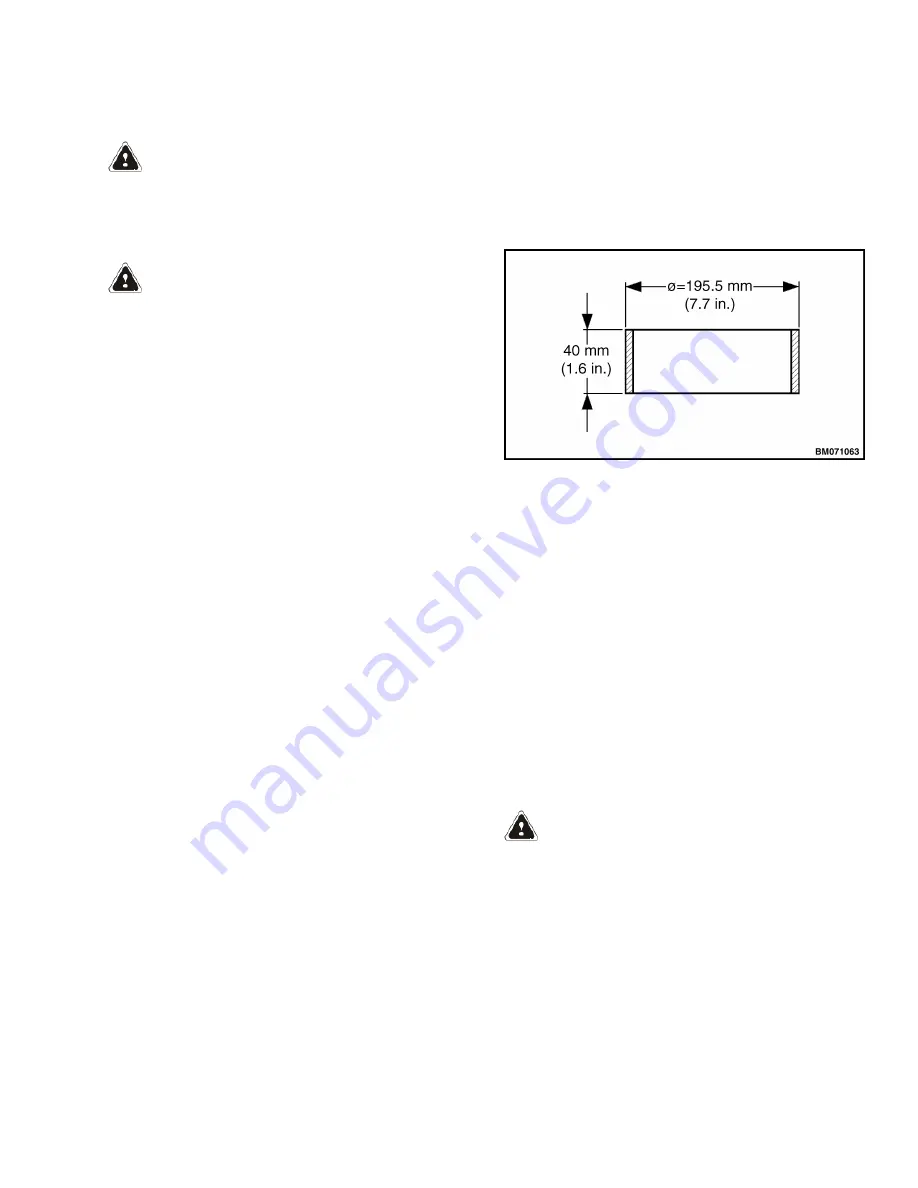
It  is  recommended  to  use  a  steel  ring  (spacer)
with  dimensions  as  shown  in  Figure  19,  but
blocks  may  be  used  as  well  as  long  as  there  is
enough  clearance  to  install  wheel  stud  com-
pletely. Support wheel hub flange where wheel
stud is to be installed with an over sized socket

or  spacer  (as  shown  in  Figure  20)  to  prevent
warping wheel hub flange.

For  lift  truck  models  H4.0FT5/FT6;  H4.5FTS5,
H4.5FT6, H5.0-5.5FT (H80, 90, 100, 110, 120FT)
(R005, S005, U005), place wheel hub as shown in
Figure 21.

Figure 19. Steel Ring

2. 

For lift truck models S4.0, 4.5, 5.5FT, S5.5FTS
(S80,  100,  120FT;  S80,  100FTBCS;  S120FTS;
S120FTPRS)  (H004,  J004),  using  a  press  or
hammer, install wheel studs. See Figure 20.

For  lift  truck  models  H4.0FT5/FT6;  H4.5FTS5,
H4.5FT6, H5.0-5.5FT (H80, 90, 100, 110, 120FT)
(R005,  S005,  U005)  apply  a  coat  of  Loctite
2760

TM

  or  Loctite  277

TM

  on  to  threads  of  wheel

stud ends threading into wheel hub and tighten
wheel  studs  to  245  to  300    N•m  (181  to  221
 lbf ft). See Figure 21.

3. 

Using  appropriate  driver  tool  install  new  seal
on to wheel bearing support. See Figure 22.

  WARNING 

Hot parts. Wear protective clothing and gloves to
prevent burns.

4. 

Place  wheel  bearing  support  on  a  flat  surface.
Heat  a  new  inboard  bearing  cone  to  80  to
90°C  (176  to  194°F).  Using  appropriate  driver
tool  install  inboard  bearing  cone  on  to  wheel
bearing  support.  Once  inboard  bearing  cone  is
cool, lubricate with multipurpose grease.

1400 SRM 1582

Reduction Gear Assembly

13

Summary of Contents for H100FT

Page 1: ...Hyster R005 H80FT H90FT H100FT H110FT H120FT Forklift Service Repair Manual...

Page 2: ...ENTIAL ASSEMBLY REPAIR WET BRAKE NMHG S4 0 4 5 5 5FT S5 5FTS S80 100 120FT S80 100FTBCS S120FTS S120FTPRS H004 J004 H4 0FT5 FT6 H4 5FTS5 H4 5FT6 H5 0 5 5FT H80 90 100 110 120FT R005 S005 U005 PART NO...

Page 3: ...dic Maintenance section Keep the unit clean and the working area clean and orderly Use the correct tools for the job Keep the tools clean and in good condition Always use HYSTER APPROVED parts when ma...

Page 4: ...ontrol Lever 39 Remove 39 Clean and Inspect 40 Install 40 Differential Repair 42 Initial Removal Steps for Differential Housing and drive axle trumpet arm right side 42 Input Pinion Carrier 42 Remove...

Page 5: ...tion is for the following models S4 0 4 5 5 5FT S5 5FTS S80 100 120FT S80 100FTBCS S120FTS S120FTPRS H004 J004 H4 0FT5 FT6 H4 5FTS5 H4 5FT6 H5 0 5 5FT H80 90 100 110 120FT R005 S005 U005 Table of Cont...

Page 6: ...ore information Please click here Then get the complete manual NOTE If there is no response to click on the link above please download the PDF document first and then click on it Have any questions pl...

Page 7: ...751 A752 B513 B514 B586 B587 B588 B589 B590 B591 B749 B750 B751 B752 B753 B754 4000SRM1250 WARNING On lift trucks with pneumatic tires completely re move air from tires before removing them from lift...

Page 8: ...3 for lift truck models H4 0FT5 FT6 H4 5FTS5 H4 5FT6 H5 0 5 5FT H80 90 100 110 120FT R005 S005 U005 8 Remove the parking brake cable Refer to the section Wet Brakes NMHG 1800SRM1597 A TOP VIEW SHOWN...

Page 9: ...FILL PLUG 3 OIL BREATHER 4 FILL LEVEL PLUG 5 BRAKE BLEEDER VALVE 6 DRAIN PLUG Figure 3 Drive Axle Drain and Fill Level Plugs for Lift Truck Models H4 0FT5 FT6 H4 5FTS5 H4 5FT6 H5 0 5 5FT H80 90 100 1...

Page 10: ...ting bolt located on top of the assembly See Fig ure 5 14 Remove the four mounting capscrews and washers from the drive axle See Figure 6 15 Remove blocks and lower the drive axle assem bly Pull axle...

Page 11: ...nce capscrews are snug begin an alternating tightening sequence between two capscrews Make sure to turn each capscrew same amount before returning to previous capscrew Before capscrews bottom out whee...

Page 12: ...6 RETAINER PLATE 7 BEARING SET 8 WHEEL HUB 9 WHEEL STUD 10 SEAL 11 SOCKET HEAD CAPSCREW 12 WHEEL BEARING SUPPORT 13 RING GEAR 14 PLANETARY CARRIER 15 PLANETARY GEAR Figure 7 Reduction Gear Assembly fo...

Page 13: ...6 RETAINER PLATE 7 BEARING SET 8 WHEEL HUB 9 WHEEL STUD 10 SEAL 11 SOCKET HEAD CAPSCREW 12 WHEEL BEARING SUPPORT 13 RING GEAR 14 PLANETARY CARRIER 15 PLANETARY GEAR Figure 8 Reduction Gear Assembly f...

Page 14: ...H4 5FT6 H5 0 5 5FT H80 90 100 110 120FT R005 S005 U005 Legend for Figure 10 1 WHEEL HUB COUPLER 2 CAPSCREWS 3 REMOVAL HOLES 4 WHEEL HUB 5 BEARING CAP 6 O RING NOTE RETAINING PLATE FOR LIFT TRUCK MOD E...

Page 15: ...k models S4 0 4 5 5 5FT S5 5FTS S80 100 120FT S80 100FTBCS S120FTS S120FTPRS H004 J004 See Figure 14 for lift truck models H4 0FT5 FT6 H4 5FTS5 H4 5FT6 H5 0 5 5FT H80 90 100 110 120FT R005 S005 U005 4...

Page 16: ...rform following step with wheel hub un der a press on a suitable support using appropriate driver 8 Pull wheel hub from wheel bearing support NOTE The wheel bearing cone will remain on wheel bearing s...

Page 17: ...ub Bearings Seal and Bearing Support for Lift Truck Models S4 0 4 5 5 5FT S5 5FTS S80 100 120FT S80 100FTBCS S120FTS S120FTPRS H004 J004 1 OUTBOARD BEARING CONE 2 OUTBOARD BEARING CUP 3 WHEEL HUB 4 IN...

Page 18: ...remove wheel studs from wheel hub with a hammer or press See Figure 17 Wheel studs for lift truck models H4 0FT5 FT6 H4 5FTS5 H4 5FT6 H5 0 5 5FT H80 90 100 110 120FT R005 S005 U005 can be removed wit...

Page 19: ...S S120FTPRS H004 J004 support wheel hub It is recommended to use a steel ring spacer with dimensions as shown in Figure 19 but blocks may be used as well as long as there is enough clearance to instal...

Page 20: ...HUB 1 SEAL 2 INBOARD BEARING CONE 3 WHEEL BEARING SUPPORT Figure 22 Wheel Bearing Support NOTE A press or hammer used with appropriate driver tool will be required for installation of bear ings bearin...

Page 21: ...RING CUP 2 WHEEL HUB 3 INBOARD BEARING CUP Figure 23 Bearing Cups Install for Lift Truck Models S4 0 4 5 5 5FT S5 5FTS S80 100 120FT S80 100FTBCS S120FTS S120FTPRS H004 J004 1400 SRM 1582 Reduction Ge...

Page 22: ...ft truck models S4 0 4 5 5 5FT S5 5FTS S80 100 120FT S80 100FTBCS S120FTS S120FTPRS H004 J004 See Figure 24 for lift truck models H4 0FT5 FT6 H4 5FTS5 H4 5FT6 H5 0 5 5FT H80 90 100 110 120FT R005 S005...

Page 23: ...R ASSEMBLY 5 WHEEL BEARING SUPPORT 6 RING GEAR 7 PLANETARY GEAR CARRIER 8 PLANETARY GEAR Figure 25 Reduction Gear Assembly for Lift Truck Models S4 0 4 5 5 5FT S5 5FTS S80 100 120FT S80 100FTBCS S120F...

Page 24: ...R ASSEMBLY 5 WHEEL BEARING SUPPORT 6 RING GEAR 7 PLANETARY GEAR CARRIER 8 PLANETARY GEAR Figure 26 Reduction Gear Assembly for Lift Truck Models H4 0FT5 FT6 H4 5FTS5 H4 5FT6 H5 0 5 5FT H80 90 100 110...

Page 25: ...00 120FT S80 100FTBCS S120FTS S120FTPRS H004 J004 See Figure 26 for lift truck models H4 0FT5 FT6 H4 5FTS5 H4 5FT6 H5 0 5 5FT H80 90 100 110 120FT R005 S005 U005 14 Repeat Step 12 through Step 13 for...

Reviews: