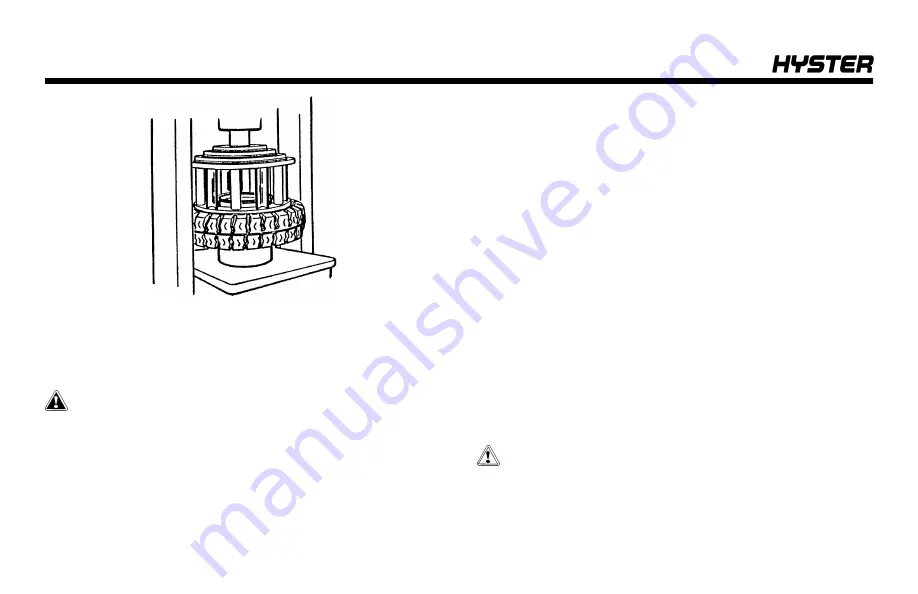
4.
Put the cage in position on the tire. Use the press to
push the tire from the wheel rim.
Install Tire on Wheel
WARNING
Damage to tire and wheel assembly and injury or death
can occur if you do not do the following procedures:
• Clean and inspect all parts of the wheel before
installing the tire.
• DO NOT use any damaged or repaired wheel parts.
• Make sure that all parts of the wheel are the correct
parts for the wheel assembly.
• DO NOT mix parts between different types or manu-
facturers of wheels.
• DO NOT mix type of tires, type of tire tread, or wheel
assemblies of different manufacturers on any one lift
truck.
DO NOT use a steel hammer on the wheel. Use a rub-
ber, lead, plastic, or brass hammer to put parts
together. Make sure that the lock ring is in the correct
position. The ends of the lock ring must not touch. The
clearance at the ends of the side ring will be approxi-
mately 13 to 25 mm (0.5 to 1.0 in.) after it is installed. If
the clearance is wrong, the wrong part has been used.
NOTE:
When disassembling wheels, see
. There
are several types of wheels used on these series of lift
trucks.
CAUTION
Too much lubricant can cause the tire to slide and
move around the wheel rim.
Maintenance
166
Summary of Contents for H40-60XT
Page 1: ...OPERATING MANUAL H40 60XT A380 DO NOT REMOVE THIS MANUAL FROM THIS UNIT PART NO 4150900 3 19...
Page 11: ...Model Description Figure 1 Model View Showing Major Components of H40 60XT Model Description 9...
Page 16: ...Figure 3 Warning and Safety Labels Sheet 1 of 3 Model Description 14...
Page 17: ...Figure 3 Warning and Safety Labels Sheet 2 of 3 Model Description 15...
Page 18: ...Figure 3 Warning and Safety Labels Sheet 3 of 3 Model Description 16...
Page 20: ...Figure 4 Controls Model Description 18...
Page 42: ...Figure 5 Dash Display Warning and Indicator Lights Model Description 40...
Page 62: ...Figure 6 Seat Adjustment Operating Procedures 60...
Page 90: ...1 DRIVE TIRES 2 STEERING TIRES Figure 10 Put a Lift Truck on Blocks Maintenance 88...
Page 92: ...Figure 11 Maintenance and Lubrication Points PSI 2 4L LPG Trucks Maintenance Schedule 90...
Page 94: ...Figure 13 Maintenance and Lubrication Points PSI 2 4L Bi Fuel Trucks Maintenance Schedule 92...
Page 115: ...Figure 16 Seat Check Maintenance 113...
Page 120: ...1 FRAME 2 PDM 3 GROUND STATIC STRAP 4 BATTERY Figure 18 Ground Static Strap Maintenance 118...
Page 137: ...Figure 30 Brake Fluid Reservoir Cover Maintenance 135...
Page 139: ...Figure 31 PDM Showing Fuses and Relays Maintenance 137...
Page 178: ...NOTES 176...
Page 179: ...Spacer 3 19 12 18 7 18 12 17 10 17 5 17 3 17 1 17 11 16 10 16 7 16 5 16 4 16 3 16...
Page 180: ...OPERATING MANUAL H40 60XT A380 DO NOT REMOVE THIS MANUAL FROM THIS UNIT PART NO 4150900 3 19...


