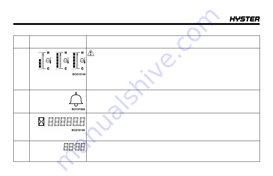
Table 2. Dash Display - Warning and Indicator Lights (See Figure 5) (Continued)
Item
No.
Item
Function
13
Coolant Temperature
Gauge
CAUTION
Do not continue to operator the lift truck when the gauge indicates that the
engine is too hot (full bars indicated, and warning buzzer beeping).
This gauge indicates the temperature of the engine cooling water. Start operation after
the engine has been warmed up and the bare gauge starts raising. When the bar
gauge reaches around the middle bar, the water temperature is optimum.
14
Alarm Set
The icon is
ON
when the alarm is on.
15
Hour Meter
Hourmeter - The hour meter operates when the key switch is in the
ON
position. Peri-
odic Maintenance recommendations are based on these hours.
16
Clock
The clock displays the current time.
Clock reset counter Enn
- If the battery has been disconnected but not reset, a coun-
ter reads
Enn
to indicate the number of days since the battery was reconnected.
Model Description
46
Summary of Contents for H40-60XT
Page 1: ...OPERATING MANUAL H40 60XT A380 DO NOT REMOVE THIS MANUAL FROM THIS UNIT PART NO 4150900 3 19...
Page 11: ...Model Description Figure 1 Model View Showing Major Components of H40 60XT Model Description 9...
Page 16: ...Figure 3 Warning and Safety Labels Sheet 1 of 3 Model Description 14...
Page 17: ...Figure 3 Warning and Safety Labels Sheet 2 of 3 Model Description 15...
Page 18: ...Figure 3 Warning and Safety Labels Sheet 3 of 3 Model Description 16...
Page 20: ...Figure 4 Controls Model Description 18...
Page 42: ...Figure 5 Dash Display Warning and Indicator Lights Model Description 40...
Page 62: ...Figure 6 Seat Adjustment Operating Procedures 60...
Page 90: ...1 DRIVE TIRES 2 STEERING TIRES Figure 10 Put a Lift Truck on Blocks Maintenance 88...
Page 92: ...Figure 11 Maintenance and Lubrication Points PSI 2 4L LPG Trucks Maintenance Schedule 90...
Page 94: ...Figure 13 Maintenance and Lubrication Points PSI 2 4L Bi Fuel Trucks Maintenance Schedule 92...
Page 115: ...Figure 16 Seat Check Maintenance 113...
Page 120: ...1 FRAME 2 PDM 3 GROUND STATIC STRAP 4 BATTERY Figure 18 Ground Static Strap Maintenance 118...
Page 137: ...Figure 30 Brake Fluid Reservoir Cover Maintenance 135...
Page 139: ...Figure 31 PDM Showing Fuses and Relays Maintenance 137...
Page 178: ...NOTES 176...
Page 179: ...Spacer 3 19 12 18 7 18 12 17 10 17 5 17 3 17 1 17 11 16 10 16 7 16 5 16 4 16 3 16...
Page 180: ...OPERATING MANUAL H40 60XT A380 DO NOT REMOVE THIS MANUAL FROM THIS UNIT PART NO 4150900 3 19...


